|
|
|
|
|

|
The internal wiring of the Fialka is very complex and extremely
difficult to reverse engineer. Almost all wires have the same
colour and are bound together in nice bundles which doesn't make
the process of tracing the wires any easier. The wiring of the
later M-125-3 machines is even more complex, due to the addition
of the NumLock switch (30 ↔ 10). Fortunately, we had access to
a partly disassembled rotor mechanism that we could take apart
in order to discover its inner secrets.
On this page we will try to explain the working principle of the
two Fialka models an how they compare to the famous
German Enigma machine.
For this we will use the block diagrams from our manual.
Should you be interested to examine the Fialka in more depth,
the full circuit diagrams are available in the
Fialka Reference Manual.
|
|
|
Block Diagram of the Enigma
|
 |
|
|
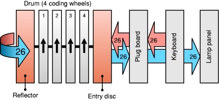
Let's consider the block diagram of an M4 Enigma
machine. At the heart of the Enigma is a set of moving cipher wheels,
called the drum, between an entry disc (right) and a reflector
(left). It uses a keyboard for input and a lamp panel for its output.
The keyboard has 26 keys (one for each letter of the alphabet).
When pressing a key, an electric current is sent from the keyboard
through a series of coding devices. First the signal passes the plug
board which allows pairs of letters to be swapped.
From the plug board,
the signal is sent to the entry disc, which passes it on to the rightmost
wheel (4), which in turn passes it to wheel 3, etc. until it hits the
reflector at the left. Inside the reflector, each contact is connected
to one of the other contacts (i.e. 13 pairs of contacts) which effectively
'reflects' the current back into the set of wheels.
The current passes all 4 wheels (in reverse direction this time),
the entry disc and the plug board, until it arrives at the lamp panel
where it will lit one of the 26 lamps.
The advantage of the use of a reflector is that it is a reciprocal
operation. In other words: the whole process is reversible.
To decode an Enigma message, one would use exactly the same
settings as those that were used to create the message in the first place.
The main disadvantage of this method however, is that a letter can
never be encoded into itself, as the return path is always different
from the entry path. This appeared to be one of the
weaknesses of the Enigma.
The design of the Fialka is similar to this, but has a number
of powerful improvements. First of all the plug board has been
replaced by a card reader (German: Kommutator) which greatly
simplifies the setup procedure. Next, the Fialka uses 10 coding
wheels and an advanced stepping mechanism.
Like on the Enigma, a reflector is used to send the current back
in to the drum, until it finally arrives at the keyboard again.
Unlike the Enigma however, a printer is used to show the final output.
However, it's not as simple as that. The Russians
clearly have learned from the flaws in the Enigma design
and have come up with some clever solutions to avoid the
principle that a letter can never be encoded into itself.
The next paragraphs will show how this was achieved.
|
|
|
Block Diagram of the M-125
|
|
|
|
In order to understand the circuit diagram, it's important
that you know how the various parts of the machine are
connected together. Consider the block diagram
of the 'simpler' M-125 machine:
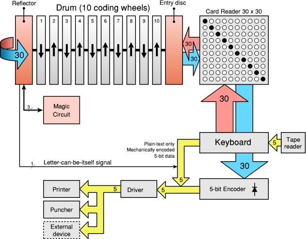
We'll start at the keyboard (centre right), which has 30 keys
in order to accomodate (a subset of) the Cyrillic alphabet.
When pressing a key, an electric current is sent to the Card Reader,
which behaves exactly as the Enigma's plug board.
From the card reader, the signal goes to the entry disc,
which passes it on to the drum. At the end (on the left)
the signal is reflected back into the drum, through the entry
disc and the card reader, until it arrives at the keyboard again.
There it is fed to a diode matrix which converts it into a unique
5-bit pattern, similar to (but different from) the 5-bit Baudot
code used on teleprinter machines. The 5-bit data from this
encoder is used to drive both the printer and the paper tape puncher.
In addition to driving one of the 30 switches, the keyboard
also contains a mechanical 5-bit encoder, which produces a
digital code (identical to the one above) of the original
plain-text letter. This code is used when the Fialka is
configured as a 'standard' teleprinter device (i.e. in plain-text mode).
However, the plain-text 5-bit code can also be used to override
the 5-bit data of the enciphered letter. This is controlled by
a single contact from the reflector. When the current hits that
particular contact on the reflector, no signal is sent back
into the drum and the 5-bit code of the original letter is used
instead.
As a result, there is a chance of 1:30 that a letter
is enciphered into itself.
In addition to this, 3 other wires from the reflector are
fed into the so-called Magic Circuit, which uses a clever
rotational principle that make the Fialka partly lose its reciprocity.
This circuit will be discussed in more detail later.
The remaining 26 contacts of the reflector are interconnected
in pairs, just like on the Enigma.
|
|
|
Block Diagram of the M-125-3
|
|
|
|
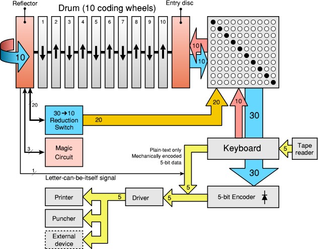
The circuitry of the later M-125-3 machines
is much more complex.
Although the machine is backward compatible with the earlier models,
some powerful new features have been added, which greatly enhances
the possibilities.
In its basic setting, the machine behaves exactly as the
old M-125 shown above.
However, the introduction of a reduction circuit,
adds the possibility of encoding messages consisting of numerical
data only (i.e. pre-coded messages). This is called numbers-only
mode. The reduction circuit is operated by a switch at the bottom
left of the machine, which is marked 30 ↔ 10.
When set to '30' (i.e. using the full set of 30 charactes) it behaves
as before. When set to '10' the keyboard is reduced to 10 keys only
(both mechanically and electrically). These are the 10 coloured keys
on the keyboard. Only 10 of the contacts of the reflector are used
(i.e. the 4 magic wires plus 3 fixed loops). The remaining 20 contacts
are fed back into the card reader on the contacts of the 20 unused keys.
This way the signal is looped around until it finally produces a usable
numerical result. Exact details of how this is achieved can be found
in the Fialka Reference Manual.
Both Fialka models have a paper-tape reader that is cleverly
integrated with the keyboard. The tape reader generates 5-bit data
from a paper-tape and feeds it to the mechanics of the keyboard,
which 'translates' it into a signal on one of the 30 switches,
just as if it was typed manually.
The same mechanics are used to generate the plain-text 5-bit data
when typing on the keyboard.
|
|
|
|
Any links shown in red are currently unavailable.
If you like this website, why not make a donation?
© Copyright 2009-2013, Paul Reuvers & Marc Simons. Last changed: Monday, 07 July 2014 - 22:26 CET
|
 |

|
|