|
|
|
|
|

|
Unknown diagnostics device
For repair and maintenance of a Fialka cipher machine,
it is likely that a special test device was available to service technicians.
This device was connected to the special test socket at the left side of the
later M-125-3 machines. For this, the existing shorting connector had to be
removed temporarily. This socket is not available on the earlier M-125
machines. So far we have never seen any kind of Fialka test device,
so we can only speculate about its functionality.
|
The test socket has 35 contact pins, divided over three rows, much like
a D-type connector. It is wired to
various parts of the Fialka, including the power supply, the keyboard encoder
and the printer. In normal use, a plastic shorting plug should be present in the
test socket (see below).
We recently found the connector that fits the test socket.
It is shown in the image on the right. The connector was probably used for the
connection of a test device. The shorting plug must be removed before the
test connector can be fitted. More images of this connector are below.
|
|
|
Inside the shorting plug (that is normally present in the socket) are 8
shorting wires. It is fixed to the socket by means of two screw terminals.
Without this plug, Fialka will not work. When removing the plug from a
working Fialka, be careful not to lose it.
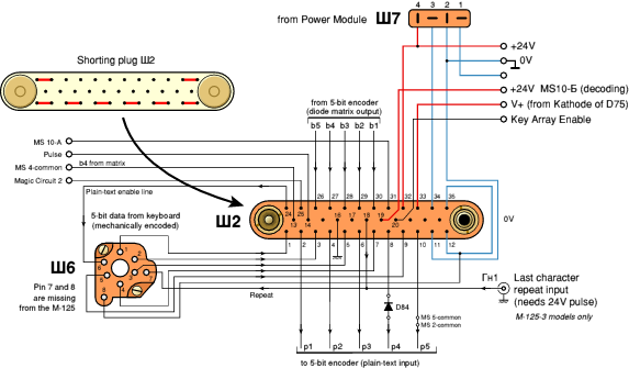
The image below shows how the shorting plug is wired and how it
should normally be fitted to the test socket.
It shows connector Ш2 when looking into
the socket from the left side of the machine.
When the shorting plug is removed, the 24V power supply is cut-off.
Furthermore, the data path from the mechanical 5-bit keyboard encoder to
the diode matrix is interrupted, so that the output of the keyboard can be
checked and test characters can be sent to the input of the printer.
|
|
|
|
Any links shown in red are currently unavailable.
If you like this website, why not make a donation?
© Copyright 2009-2013, Paul Reuvers & Marc Simons. Last changed: Monday, 07 July 2014 - 06:43 CET
|
 |

|
|