|
|
|
|
|

|
Body wearable intercept receiver
Filin (Russian: Филин) is a Russian body-wearable intercept receiver that
was used during the Cold War to track down,
locate and intercept enemy communication.
The eavesdropping receiver was developed around 1970 and was available in
three different versions, each with its own frequency
range. The version shown here was used by the East-German Secret Police
(Stasi).
Like most secret Russian equipment, it was named after a bird.
Filin is the Russian word for owl.
|
The case of the receiver is curved, so that it can easily be worn on the
chest, concealed under the operator's clothing. This way an interceptor
could approach an enemy surveillance agent or a clandestine transmitter
without being noticed.
Three versions of the Filin are known to exist, each with its own frequency range (see below).
The image on the right shows a typical Filin intercept receiver that was used
by the Stasi,(Ministerium für Staatssicherheit, Secret Police),
of the former DDR (East-Germany).
It was improved by the Germans in several ways.
|
|
|
The most obvious modification is the addition of a switchable amplifier
at the bottom of the receiver. It makes the unit more sensitive to weak
signals and is backwards compatible. On its side is a switch with 2 positions:
Nah (near-field) and Fern (far-field).
In the Fern-position the amplifier is enabled.
In the Nah-position it is bypassed.
The East-Germans also replaced the (rare) Russian coax connectors by the
more common BNC sockets that were generally available in the DDR. The
antennas were also modified with BNC connectors.
When unused, the receiver was usually packed inside a
small suitcase,
together with all of its accessories, such as cables, batteries,
filters and headphones. Various models of suitcases were used for this
purpose, ranging from small compact cases to full-size suitcases.
It is not known how many Filin receivers were deployed, but for a long
time it was one of the most popular portable direction finders in the
countries of the Warsaw Pact. Other Russian direction finders were
developed to allow higher frequencies and frequency hopping radios to
be intercepted, such as Soyka
and Sinitsa,
but these were built in far smaller quantities.
|
|
|
|
|
|
|
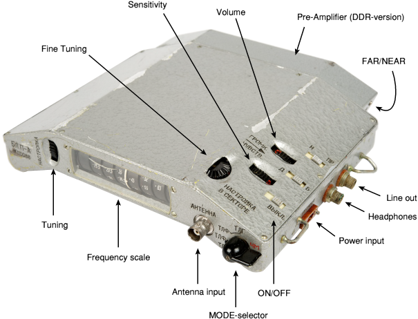
In order to put the receiver to work, connect a 12V power source to the
power input socket (ПИТАНИЕ) and connect the speaker to the
headphones socket (ТЕЛЕФОН). Next turn on the unit by sliding the
ON/OFF switch inwards. Set the MODE-selector to the desired type of
modulation, AM
or FM
(ЧМ),
and signal type, PHONE (ТЛФ)
or TONE (ТЛГ).
The latter is used for intercepting
morse signals (telegraphy)
or for producing a constant tone when homing in on the transmitter.
Now set the TUNING and FINE-TUNING controls to the desired frequency.
The receiver is now ready for use. Please note that you may have to
adjust the volume and sensitivity controls.
|
As far as we know, three different versions of Filin were made, each with
its own frequency range. They are designated by the first three letters of
the Cyrillic (Russian) alphabet: A, B and V (or in Russian: А, Б, В).
The model is engraved on the left of the top panel of the receiver.
|
The image on the right shows a typical top panel of a Filin model-A.
It is marked as БЛ.П-А, which is the abbreviation of
Блок Приемник-А (Unit Receiver-A).
The serial number is engraved directly below the model designator (110088).
- Filin A (А)* / 24-63 MHz
- Filin B (Б)* / 60-150 MHz
- Filin V (В)* / 148-308 MHz
*) Russian designator
|
|
|
|
Inside the lid of the suitcase was a
checklist with all items and their location.
Various layouts of the case exist and a different number
of accessories was supplied with each version of the receiver (depending
on the frequency range). Furthermore, the contents were changed and items
were swapped for alternatives regularly without altering the checklist.
The drawing above shows one of the case layouts that was used.
The list below has been compiled from various checklists found
inside the top lid of the cases. It shows the location number of each item
in brackets at the end of each line.
This number corresponds with the drawing above.
The number is also imprinted at the bottom of the case.
|
- Приемник: Receiver (1)
- Блок питан. аккум.: Rechargeable battery (6)
- Ремень: Belt (7)
- Антенна V: 2 x V-Antenna (8)
- Антенна Штюрь: Rod antenna (8)
- Блоцк Питан. Бат.: Battery block 3 x 4.5V (9)
- Телефон: 2 x Speaker (10)
- Кабель (l: 800): Cable (9)
- Отвертка: Screwdriver (ED 76-09) (11)
- Отвертка: Screwdriver V 150 x 0.4 (12)
- Фильтр: HF Filter (5)
- Power converter (2)
- Комплект запасн. частей: Set of spare parts (8)
|
Please note that different layouts were also used and that
certain parts were sometimes stored in a different place.
During the receiver's lifetime, some parts were removed and other were
added.
The items in the bottom part of the case are held in place by means
of leather straps.
Location (2) is hidden under item (1).
A leather belt (7) is supplied to allow the receiver to be carried
on the chest. Position (4) is believed to be reserved for an extra filter
or for the indicator.
The purpose of position (3) is unclear.
It is possible that it was used to store an (optional) battery charger.
Warning:
Never carry the suitcase by its handle.
The grip of the suitcase is made of poor-quality plastic which has
become brittle after all these year. Carrying the suitcase by the grip,
might cause it to break. As a general rule: never carry a museum piece
by its grip.
|
|
|
|
|
|
|
Filin could be powered in various ways. It is typically be powered by
a 12V DC source connected to the socket marked Питание (Power)
on the side of the receiver, but accepts any DC voltage between 9 and 15V.
It comes with two types of batteries: A rechargeable battery block and
an assembly, packed in green cloth, to carry three flat-pack 4.5V batteries.
|
The rechargeable battery consisted of a bakelite box with 7 cells of
1.5V each. This gives a total of 10.5V. Like the receiver itself,
the bakelite box was also curved, so that it could be worn on the body,
attached to the belt.
Unfortunately, the rechargeable battery is missing from our Filin,
so we can not show a picture of it at present.
As an alternative, an assembly was supplied that allowed three standard
flat-pack 4.5V dry batteries to be connected in series, producing a total of
13.5V. The flat-pack battery assembly is shown in the image on the right.
|
|
|
The total assembly would be packed inside a green cloth bag
that could be attached to the belt. Under certain conditions, such as sub-zero
termperatures, dry batteries are preferred over rechargeable ones.
Furthermore, the higher voltage of the dry batteries (13.5V) would make the
battery last longer than the (10.5V) rechargeable one.
|
The receiver could also be powered by an external source,
such as the battery of a car or truck.
A special power connection box (2)
was supplied for this purpose. The box has a switch that allows selection
between 12V and 24V.
The box is shown in the image on the right.
One side of the box is connected to the external 12V or 24V source.
The other side has a typical 4-pin rectangular plug that mates with the
power input socket of Filin (ПИТАНИЕ).
The switch on the front panel of the box
should be set to the correct voltage 12V (12В)
or 24V (24В).
|
|
|
The box contains
a simple power-divider with two 5W resistors, a diode
(for protection against reverse polarity), a 250 mA fuse
and a two-pole-double-throw switch. The latter is used to bypass the
circuit when 12V input is selected.
The circuit diagram is given below:
|
With some Filin receivers a small device marked ИНДИКАТОР (indicator)
has been found. This device is not listed on the checklist.
The device has two sockets at the front. The socket on the left
is marked ВЫХ. (output) and the socket on the right is marked
ПИТАНИЕ (power supply).
|
At the top is a voltage meter and a switch to select between output
and power supply.
The indicator serves two purposes. It can be used to check the condition
of the battery. For this the battery is connected to the rightmost socket
market ПИТАНИЕ
and the switch is set to ПИТ.
When using the receiver is an operational context, the indicator can also be
used as a field-strength meter. It should then be connected to the line output
of the receiver (ЛИН) by means of the supplied
short cable,
that is shown in the images below.
|
|
|
When we acquired our Filin receiver, the indicator was broken. The receiver
had been stored in a moist place for many years. As a result, many parts
were oxidized and the meter was completely blocked. The scale of the meter
had swollen so much that it was beyond repair.
In order to bring the indicator back to life,
we replaced the meter
by a similar (Russian) type of the same era.
The image above shows the circuit diagram of the indicator.
It is clearly visible that the box contains two seperate circuits.
The upper circuit is the battery condition meter. Resistor R1 is used
to create an artificial load, whilst R2 is dimensioned to give a proper
reading on the voltage scale.
The lower section is the field-strength meter. D3 is a zener diode
that protects the meter (M1) against excess voltages.
The circuit is shown here with the switch (S1) set to ПИТ (voltage).
As we swapped the meter (M1) for a different type, we had to change
R2 and R3 accordingly.
It is not clear where the indicator was stored inside the suitcase.
One possibility is that is was stored in position (6), instead of the
rechargeable battery pack. Another possible location is (4) which has
the proper footprint for the indicator, but is a bit too close to
the receiver (1).
|
|
|
|
|
|
|
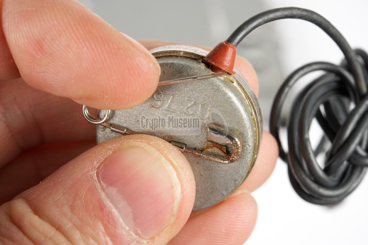
According to the checklist, the receiver was supplied with
two identical headphones. The headphones that were found with many
Filin receivers in recent years, are all small high-impedant speakers
that can be attached to the clothing by means of a safety pin at the rear.
|
The image on the right shows a typical Russian louspeaker that was supplied
with Filin. At the rear it has an integrated safety pin, allowing it to
be attached to the operator's clothing.
The speaker has a diameter of approx. 3 cm and should be attached close
to the operator's ear (e.g. under the collar of a coat). The cable is about
70 cm long and has a rather strange (rare) plug at the end. It connects to the
side of the receiver to a connector marked ТЛФ (telephone).
A similar connector, marked ЛИН (line), is available for connecting a
recording device.
|
|
|
The line connection (ЛИН) can also be used for connecting the second
speaker (when available).
The speaker, and hence the connector, is often missing from Filin
receivers found today. As they are extremely hard to find, we've
supplied the drawing below, so that an alternative can be made.
The same connector is used on the Sinitisa
intercept receiver and the UFT-421
covert radio.
The speaker is relatively high-impedant (approx. 2000 ohm) and
produces a loud signal.
If the speaker appears to be dead, it can easily be checked with a
multi-meter. The (DC) resistance should be approx. 200 ohm.
In many cases, the wires inside the connector are broken.
|
|
|
|
|
|
|
Filin was supplied with a leather belt that allowed the receiver to
be worn on the chest. The belt has 4 hooks (2 at either side) that are
attached to the metal brackets at the corners of the receiver,
as shown in the image on the right.
In the middle, the belt has a buckle that can be used to adjust it
to fit tightly around the waist.
Over time, different designs of belts were supplied.
The images below show a brown belt
with safety catches
and a simple black hook-on belt.
|
|
|
|
Filin is built inside a die-cast aluminium frame, with aluminium
covers at the front and rear. The interior is exposed when the front
and rear panels are removed. This is done by removing the small bolts
at the edges of the panels.
The image below shows the font side of the interior.
|
The frequency dial, which is normally at the top, is shown here at
the bottom. At the bottom right are the controls.
The various pre-amplifiers, filters and IF-sections are housed inside
a series of shielded boxes. At the top right
is the power supply
that generates the necessary voltages.
In order to improve the reception of weak signals, the Stasi (secret
police) of the former DDR (East-Germany) added an extra 2-stage
pre-amplifier
which is bolted to the bottom of the receiver.
It allows Filin to be used at greater distances from the
intercepted object.
|
|
|
The pre-amplifier is curved in the same way as the receiver itself and
can be accessed from the bottom, by removing
an aluminium panel. The antenna signal from the BNC connector on top of
the unit, is fed directly to the pre-amplifier. The output of the amplifier
is then used as input to the receiver.
Operation of the pre-amplifier can be controlled by a small slide-switch
mounted at the side. It has two positions: FERN (FAR, pre-amplifier enabled)
and NAH (NEAR, pre-amplifier bypassed). It is the only switch that is marked
with German text rather than Russian.
|
We are still looking for the user manual and the technical manual (including
circuit diagrams) of this receiver.
We are also looking for on original bakelite battery box.
If you have any of these available, or if you have additional information,
please contact us.
|
- Paul Reuvers and Marc Simons, Filin-A portable intercept receiver S/N 110088
Crypto Museum, Investigation March 2012.
- Louis Meulstee, USSR Portable Intercept Receivers
Wireless for the Warrier. Volume 4. September 2004. ISBN 0952063-36-0.
|
|
|
|
Any links shown in red are currently unavailable.
If you like this website, why not make a donation?
© Copyright 2009-2013, Paul Reuvers & Marc Simons. Last changed: Sunday, 04 May 2014 - 23:01 CET
|
 |

|
|

 body-wearable intercept receiver")


")


