|
|
|
|
|

|
Programmable Precision Measurement Receiver
Minilock 6900 is a digital programmable precision measurement receiver,
developed and built by Schlumberger in M³nchen
(Germany) in the mid-1980s.
The 6900A was an improved version of the nearly identical 6900.
The receiver covers all
frequencies between 10 kHz and 1000 MHz and supports all common modes,
including AM, FM, PM, USB and LSB with a variety of bandwidths.
|
The receiver was commonly used by a number of agencies around the world,
for interception and fingerprinting of suspicious radio signals.
The unit shown in the image on the right was used for many years by the
Bundes Nachrichtendienst (BND),
the German Intelligence Service.
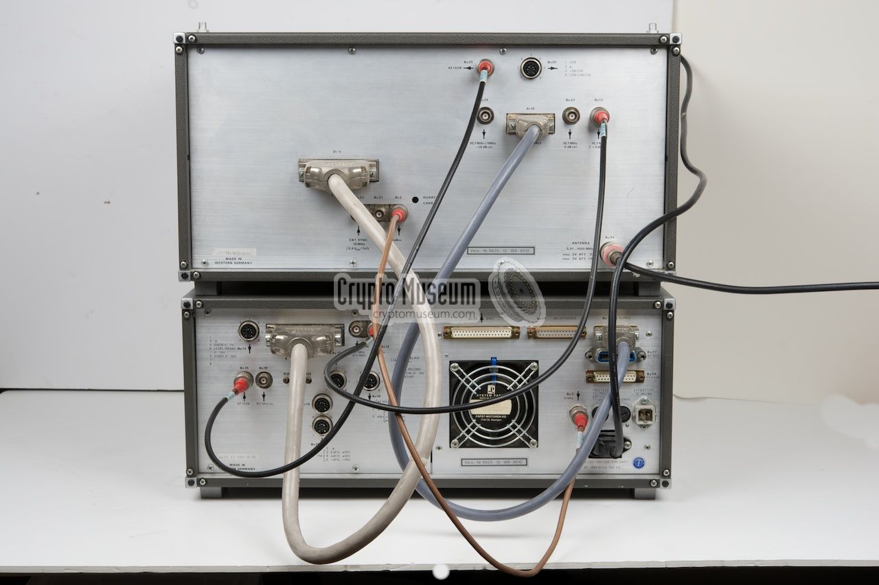
The main radio consists of two units: a large one, which contains the
actual 6900 receiver, and a smaller one, that contains the 6902 control panel.
The two units are connected by a series of cables
at the back.
Optionally, a panorama viewer was available as a third unit.
The device can be fully controlled via de control panel on the 6902 unit,
but also externally by a computer, using the RS-232 (V.24) or the IEC interface.
A printer (with parallel interface) can be connected for logging purposes.
|
|
|
All connections are at the back
of the two units, with the exeception of
the 3mm jack socket for an external speaker or headphones, which is located
at the bottom right of the front panel. By default the internal speaker is
used. All controls are located at the front of the 6902 CONTROL UNIT.
The front panel consists of two sets of controls: the main control
panel (see below) and a small panel at the right.
The small panel holds
the rotary dial, which is used to alter the frequency and other settings,
the power switch, a standby switch and the volume control. Please note
that the volume control needs to be
pushed-in in order to enable the
speaker.
|
|
|
|
|
|
|
The largest part of the front panel is taken by the main control panel.
It consists of a wide red alphanumeric LED display, two analogue meters
and a keypad that sticks out at the front, so that it can be operated
easily by the user. The keypad also contains the MODE indicators at
the left.
All operations are identified by a two-letter combination, that can be
entered on the MODE selection keypad.
A yellow LED, at the left of the keypad,
shows whether an operation is enabled. For example: to enable the
40dB input attenuator (C4), the sequence
[S] [C] [4] [ENT] is used.
The frequency can be entered in several ways. First the [F]
key needs to be pressed, after which a digit of the frequency display
starts flashing. The cursor keys [<] [>] can now be used
to select the required digit (i.e. the step size). Next, the digit can
be altered by using the rotary dial, the [+][-] keys, or the
numerical keys on the keypad.
When finished, press [ENT] to complete.
|
- 6900, Minilock RF Unit
- 6901, Panorama viewer 1
- 6902, Control Unit
- 6907, Television IF interface 1
- 6906, Antenna switcher (6940) interface 1
- 6940, Antenna Switcher 1
|
The Control Unit is the smaller of the two units. It measures
444 x 192 x 490 mm, weights 20 kg and fits a standard 19" rack.
It contains all controls, meters and indicators on a clear
well layed-out control panel, with a bright crisp red alphanumerical
LED display at the top.
The control panel can be detached and operated remotely by using
an (optional) extension cable. Furthermore, the entire radio can
be controlled from, say, a computer, using the V.24 (RS-232) and
IEC interfaces. The Control Unit is connected to the 6900 RF Unit
with 5 cables at the back.
|
|
|
|
The RF Unit is the larger of the two units. It measures
444 x 236 x 490 cm, weights 19 kg and fits a standard 19" rack.
It contains all HF, IF and AF components and is controlled
by the 6902 Control Unit. The antenne should be connected to
the N-connector at the rear.
|
The 6900 RF Unit is usually placed on top of the 6902 Control
Unit, so that the control panel is easily accessible when the
reciever is placed on a table. It is also possible however,
to place the RF Unit under the Control Unit. Furthermore,
the Control Panel can be detached.
In order to obtain maximum precision and accuracy, the receiver
uses its own built-in temperature stabilized 10 MHz reference
oscillator. A few minutes after turning the receiver on, the
stability of the reference oscillator is good enough for general use.
|
|
|
Maximum stability however, is obtained after several hours.
For this reason, the receiver can be put in STAND BY when
unused, by means of the ST BY switch.
This leaves the reference oscillator powered.
The Control Unit is locked to the same 10 MHz
reference signal via a coax cable at the back. If an even better
precision and stability is required, the internal reference
oscillator can be locked to an external 10 MHz source, e.g.
from a Rubidium, DCF or GPS Standard.
|
|
|
|
|
|
|
- Frequency range: 10 kHz - 1000 MHz
- Resolution: 10 Hz
- Stability: 10-7 after 20 minutes at 25°C
- Temperature drift: < 2.10-9/°C
- Long term drift: < 3.10-9/Day after 6 weeks
- External synchronisation: 10 MHz, 0.2 V into 2K
- IF bandwidth: 1, 8, 13, 16, 125 and 250 kHz
- A1 bandwidth: 400 Hz
- SSB bandwidth: 2.4 kHz
- Preselection: 0.01, 1, 3, 3, 10, 15, 20, 25, 30, 140, 270, 520, 680, 840 and 1000 MHz
- 1st IF: 629.3 MHz (10 kHz-520 MHz) or 229.3 MHz (520-1000 MHz)
- 2nd IF: 10.7 MHz
- HF input impedance: 50 Ohm
- VSWR: < 1.2 (attenuator ≥ 10dB), < 2.5 (attenuator 0dB)
- Noise level: 20dB (low-distortion mode), 12dB (low-noise mode)
- Intercept point: +18dBm (low-distortion mode), +3dBm (low-noise mode)
- Adjacent channel suppression: > 80dB (CEPT)
- Modulation types: AM, FM, PM (ΦM), SSB (USB, LSB, ISB), CW
- Mains voltage: 110, 120, 130, 220, 230, 240 V
- Operational temperature range: 0 to 45°C
- Storage temperature range: -25°C to +65░C
|
- 6900: 444 x 236 x 490 cm, 19 kg
- 6902: 444 x 192 x 490 cm, 20 kg
|
-
Due to the size and number of large circuit diagrams,
only the index is published here.
|
|
|
|
Any links shown in red are currently unavailable.
If you like this website, why not make a donation?
® Copyright 2009-2013, Paul Reuvers & Marc Simons. Last changed: Saturday, 01 December 2012 - 17:17 CET
|
 |

|
|


")

")
")

 and the 10MHz reference signals.")