|
|
|
|
|

|
Panoramic Monitoring Receiver
PAN-1000 was a high-end intercept receiver in a 19"
rackmount case, designed and built by
Nederlands Radar Proefstation
(NRP, Dutch Radar Laboratory),
in the early 1980s, especially for
the Dutch Radio Monitoring Service, the so-called
Radio Controle Dienst (RCD),
of the Dutch Post Office (PTT).
They were used for finding clandestine radio stations (pirates).
The radio is also known as the NRP receiver.
Only a small number of these custom-made receivers were built.
|
The RCD
was responsible for tracking down and confiscating
clandestine radio stations in The Netherlands. As good high-quality monitoring
receivers were not commonly available in those days, the RCD decided to have
their own feature-packed receiver developed by the
NRP.
Development took several years and the ordered units were delivered over
a period of five years. The image on the right shows a complete PAN-1000
system, consisting of a
large 19" rack with the
various HF, IF and AF modules,
a small PSU,
a display
and a custom-designed control unit.
|
|
|
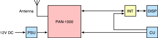
The PSU and the receiver were usually mounted in the trunk,
with two thick cables running to the front of the car.
The display (DISP) was connected to the PAN-1000 receiver via a large interface
unit (INT), and the Control Unit (CU) was connected to both the display
and the main unit.
The block diagram above shows how the various components are connected.
All controls are located on the CU, except for the preset buttons and
the brightness control, which are part of the display.
When in use, the complete set consumes slightly less than 6A (at 12.6V).
From 1983 to 1987, between 30 and 40 PAN-1000 units were built by
the NRP
[1], for a price of NLG 160,000 each (approx. EUR 73,000).
The exact number of receivers is unknown at this time, as spare units
and additional units were built for other Government agencies as well.
During the 1990s, when new intercept receivers were needed, the PAN-1000
was considered too expensive. As a replacement, the ICOM 9000 receiver was
expanded with a control unit, the Elcom PAN 2000 FFT display, and a remote
control unit that was similar to the Control Unit of the PAN-1000.
This setup was often combined with a TAIYO direction finder.
|
|
|
|
|
|
|
The complete PAN-1000 system was designed in such a way that it could conveniently
be built inside the Ford Grananda and Peugeot 204 cars that were used
by the agency at the time. The drawings below show the position of the
various components inside the Ford Granada in 1984.
The 19" racks (1) and
(2) are mounted in the trunk.
The interface between the receiver and the display would be fitted inside
the glove compartment (3) of the car,
whilst the display itself was mounted on the dasboard (4). Finally, the
remote control unit was mounted between the seats,
just aside the handbrake (5).
The antenna was mounted somewhere on the body of the car (6).
|
|
|
The PAN-1000 receiver in use
|
 |
|
|
The PAN-1000 covers all frequencies between 100 kHz and 1 GHz and was
suitable for virtually any intercept job at the time, although it
did not have Direction Finding (DF) capabilities. Instead, the operator would
measure field strength, in combination with a set of attenuators and
a high-resolution field strength meter (with a linear or logarithmic scale)
on the main plasma display.
|
The attenuator
could be selected directly from the CU. Additionally,
the field strength meter could be switch from a logarithmic scale to
a linear one, giving a much better resolution in close proximity of the
clandestine transmitter.
The entire system was designed in such a way that it could be
controlled by a single person who was driving the car at the same
time. For this reason, cars with an automatic transmission were
generally used. The frontmost dial is used for tuning to the
desired frequency in small steps. Push-buttons are used for
larger steps.
|
|
|
Once the receiver was tuned to the desired radio station,
the investigator would start driving in order to find a direction
in which the signal strength would increase. If the signal became too
strong, he would use the second dial to select an appropriate
attenuator (between 0 and 120 dB).
Finally, when the receiver was in close proximity of the transmitter,
the attenuator would be set to its maximum (120 dB) and the S-meter
would be switched to linear scale. Whilst driving past the location
of the transmitter, the meter would clearly indicate a peak value.
The investigator would usually repeat the last step several times,
to be sure that he entered the right house.
|
The main unit of the PAN-1000 system is the actual receiver itself.
It has a modular design and consists of a double Eurocard 19" rack
that holds the various modules.
Each half of the rack has its own backplane through which the power
lines and clock signals are distributed.
|
The image on the right shows the main unit of the PAN-1000 system.
The case contains 19 modules, divided over two rows. The antenna
is connected to the N-connector at the top left. From there the
input signal is fed through a switchable attenuator and fed to the
various other modules by means of teflon coax cables.
All HF and IF connections between the various modules are made
by means of a large number of short high-quality teflon coax cables
and SMA connectors. The rack allows each module to be removed in
order to be serviced individually.
|
|
|
The receiver has no controls and was usually mounted in the trunk
of the car. Two long multi-wire cables are used to connect the
Control Unit (CU), the Display and the interface (INT), which are mounted inside
the cabin, within reach of the driver who is also the operator
of the radio.
|
The simplified block diagram below shows how the various modules
are connected together. The frequency range from 100 kHz to 1 GHz
is divided over six main bands. The input selector feeds the
antenna signal, via an adjustable attenuator, to one of these band modules.
Within each module, the band is further divided into sub-bands that
are each processed independently.
|
The Control Unit (CU) measures approx. 26 x 7.5 x 11 cm
and was custom designed in such a way that all controls were conveniently
located. It was mounted in between the two front seats of the car,
with a few strips of velcro, so that it could easily be removed and hidden.
|
The image on the right shows the CU when seen from the right.
The driver could place his right hand on the CU whilst driving the car,
using the grey plastic stub (at the left) as a hand rest.
The two most prominent controls are located at the top of the CU.
The frontmost dial is the tuning knob and the other one is the
attenuator. The three knobs at the lower right are (front to rear)
clarifier, volume and squelch. The MODE
selector (AM, FM, SSB) is
located at the back of the unit, as it is hardly used.
Various toggle switches and push-buttons are located at all sides of the
CU, within reach of the fingers.
|
|
|
There is no text or legend on the CU, as the driver has no time
to look at the controls. Besides the PAN-1000 was often used in
the dark. In practice, an operator would quickly get aqcuainted
with the controls as they are organized in an intuitive manner.
All connections to the main unit and the display interface and the speaker are
at the rear, where also the MODE selector is located.
An isolated recording output (0dB into 600Ω)
is available on a 5-pin DIN socket at the right side.
|
The display unit is used for the interaction with the operator.
It shows the current frequency, the current settings and the
panorama display. At the heart of the display unit is a SHARP LJ-320U01
Electro Luminescent (EL) display, commonly called PLASMA,
with a resolution of 320 x 240 pixels.
|
The display measured approx. 19 x 15 cm and was mounted on the
dashboard of the car, to the right of the steering wheel, in such
a position that the driver had a clear view.
The display contains the necessary electronics
for driving the display and for generating characters.
In addition, a large microprocessor based interface had to be installed
not too far away from the display; generally in the glove compartment
or below the passenger seat. The maximum distance is dictated
by the relatively short display cable that is visible in the image.
|
|
|
Below the display are 7 push-buttons.
The first six of these buttons are for recalling the presets.
The rightmost button is green and is used for storing a new preset.
After pressing the green button, the letter 'M' appears in the
display (Memory).
After subsequently
pressing one of the preset buttons,
the current frequency is stored and the letter 'M' disappears again.
|
A seperate Power Supply Unit (PSU) was supplied with the PAN-1000
receiver. According to the front panel, it is known as MODULE 20.
The task of the PSU is to supply the 12V DC voltage from the
car battery to the receiver, via a relay that is controlled
with a switch on
the Control Unit (CU).
|
The PSU also delivers the +15V and -12V DC voltages needed for the
A/D converter and the Panoramic EL Display.
The image on the right shows the PSU, which is actually a single
Eurocard module, fitted in a narrow 19" rack.
The PSU was usually
mounted in the trunk of the car, and coud not be removed.
A connector at the back of the PSU leads to a small connection
panel with a 2-pin socket for the 12V DC supply from the car, and
an 8-pin socket for connection to the receiver.
A detachable cable
was used to connect the Main Unit to the PSU,
allowing the receiver to be removed easily when necessary.
|
|
|
The PSU is designed in such a way that the PAN-1000 consumes no
power when it is switched OFF. This is done by deactivating the
relay that is present inside the PSU.
When toggling the power switch at the
front of the Control Unit,
the relay is activated and power is supplied to the receiver
and the other parts. Within a few seconds, the PAN-1000 is ready
for use.
|
|
|
|
|
|
|
The history of the PAN-1000 receiver starts in the early 1980s,
at a time when The Netherlands was undergoing a recession and
was plagued by an increasing number of clandestine radio and TV
stations, often indicated as 'pirates'. At the time,
the Radio Controle Dienst (RCD),
responsible for confiscating such illegal transmitters,
was heavily understaffed and had virtually no budget.
When the current State Secretary of Transport,
Mrs. Neelie Smit-Kroes [4], visited the RCD's headquarters in Nederhorst
Den Berg (Netherlands) at the end of 1980 or the beginning of 1981, the
managing director of the RCD, Daan Neuteboom, expressed his concern about
the lack of personnel and budget. When Mrs. Kroes asked him how many new
staff he needed, he stared at the ceeling for a moment and answered:
"Fourty, Madam State Secretary". Although he probably didn't expect it,
Kroes answered: "You will get your fourty men, Mr. Neuteboom!" [2].
From then on, a seemingly endless line of new employees entered service.
At the same time, it was decided to professionalize the department and
develop a state-of-the-art receiver.
A small committee was assembled to draw the initial
functional specification, using an existing Hans Plisch receiver as a
starting point.
It would have to be a panorama receiver with an operational frequency
range from 100 kHz to 1GHz, and it had to fit inside a standard car.
The new receiver was called PAN-1000 and would be
developed and built (in small quantity) by the Dutch Radar Test Station,
Nederlands Radar Proefstation (NRP)
in Noordwijk (Netherlands).
Development of the receiver at the NRP started around 1983 and the first units
were delivered in 1984. Apart from the extreme electrical specification,
several problems had to be solved. The first one was the real-time panorama
display, as LCD screens were way too slow at the time.
This problem was solved by using a high-speed amber plasma display
driven by a separate interface.
|
Another problem was that the complex receiver had to be controlled
by the operator whilst driving the vehicle. This time
Cor Moerman came to the rescue. He devised a mockup of
a control unit, made from PCB material [5],
that could be fitted in between the front seats of the car,
with the various controls positioned intuitively [3].
After modifying the design several times, the controller was finalized
and sent to the NRP who made it into a real control unit.
The image on the right shows Cor Moerman's empty mockup aside the final
Control Unit made by the NRP.
|
|
|
Finially, in May 1984 the PAN-1000 was ready for
release and the first units were delivered to the RCD.
They were built into the existing intercept vehicles of the time:
a series of Ford Granada and several Peugeot 204 cars.
Production of the PAN-1000 receivers was rather slow, and
the first 10 units were delivered over a period of several years.
In 1987, another 21 units were built.
|
The RCD was the Dutch Radio Monitoring Service (Radio Controle Dienst),
responsible for tracing radio and TV interference, and for confiscating
clandestine radio and TV stations. In the early 1980s, The Netherlands
was flooded with pirates and the PAN-1000
receiver was developed.
Although the name of the organization has changed frequently
over the past years, it is often still called RCD by the public.
The agency is currently known as Agentschap Telecom (AT).
 More about the RCD More about the RCD
|
|
|
|
The NRP was the Dutch Radar Test Station (Nederlands Radar Proefstation)
in Noordwijk. It was established by Mr. J.M.F.A. (Joop) van Dijk
shortly after WWII, on 7 July 1947, in an attempt to bring The Netherlands
up to speed with the wartime developments in the field of RADAR.
In the years that followed, the NRP was involved in development and consultancy
in the field of RADAR, navigation, sensors, communication equipment and
communication systems in general. In the early 1980s the NRP was asked to
develop a high-end intercept receiver for the Dutch Radio Monitoring Service
(RCD).
More about the NRP
|
|
|
Recording
The Control Unit (CU) has a 5-pin 180° DIN socket
at the right side, just behind the SQUELCH control.
This sockets is wired for MONO recording and is completely
isolated from the receiver, by using a 1:1 transformer.
It supplies AUDIO, independent from the VOLUME control,
at a line level of 0dB into a 600 Ω load.
Pinout is as follows (looking into the socket):
Speaker
The connection for the speaker is at the rear of the CU,
where also the connections to the display unit and the
receiver are. The audio amplifier can deliver 2W into a
4 Ω speaker.
The speaker connection is a 5-pin 207° socket
with the following pinout:
|
- WBFM (100 kHz)
- NBFM (12 kHz)
- AM (5 kHz)
- LSB (2.4 kHz)
- USB (2.4 kHz)
- CW (using USB or LSB)
|
Below is a complete list of the various modules of the PAN-1000.
Modules 1 thru 19 are part of the main unit.
The other modules are available as separate units.
|
- Input selector
- Converter 500-1000 MHz
- Converter 250-500 MHz
- Converter 125-250 MHz
- Converter 62.5-125 MHz
- Converter 31.25-62.5 MHz
- Converter 0.1-31.25 MHz
- 50 MHz Selector Unit
- IF Converter
- IF Amplifier and Demodulator
- Logarithmic Amplifier
- Mixer Panorama Display
- Sweep Synthesizer
- Microprocessor
- 240-360 MHz Synthesizer
- 400-960 MHz Synthesizer
- 50-86.25 MHz Synthesizer
- 49-85.25 MHz Synthesizer
- 100-110 MHz Synthesizer
- DC-DC Converter (PSU)
- Control Unit (CU)
- Display Interface Unit (INT)
- Panorama Display (DISP)
|
|
AF
|
|
Audio Frequency
|
|
HF
|
|
High Frequency
|
|
IF
|
|
Intermediate Frequency
|
|
NRP
|
|
Nederlands Radar Proefstation
Dutch Radar Test Station in Noorwijk (Netherlands). Established in 1947 and renamed to
CHL (Christiaan Huygens Laboratorium) in 1993. Now located in Katwijk (Netherlands). More...
|
|
RADAR
|
|
Radio Detection and Ranging
|
|
RCD
|
|
Radio Controle Dienst
Radio Monitoring Service of the Dutch Post Office (PTT) from 1975 to 1989.
Since renamed to Agentschap Telecom (AT) and now part of
the Ministry of Economics. More...
|
-
Manual reproduced here by kind permission of CHL [6],
the successor of the NRP.
|
|
|
|
Any links shown in red are currently unavailable.
If you like this website, why not make a donation?
© Copyright 2009-2013, Paul Reuvers & Marc Simons. Last changed: Saturday, 01 February 2014 - 09:28 CET
|
 |

|
|


 with connection panel")
")


")


 with connection panel")


 and actual (right) PAN-1000 Control Unit")
")

, looking into the socket.")

