|
|
|
|
|

|
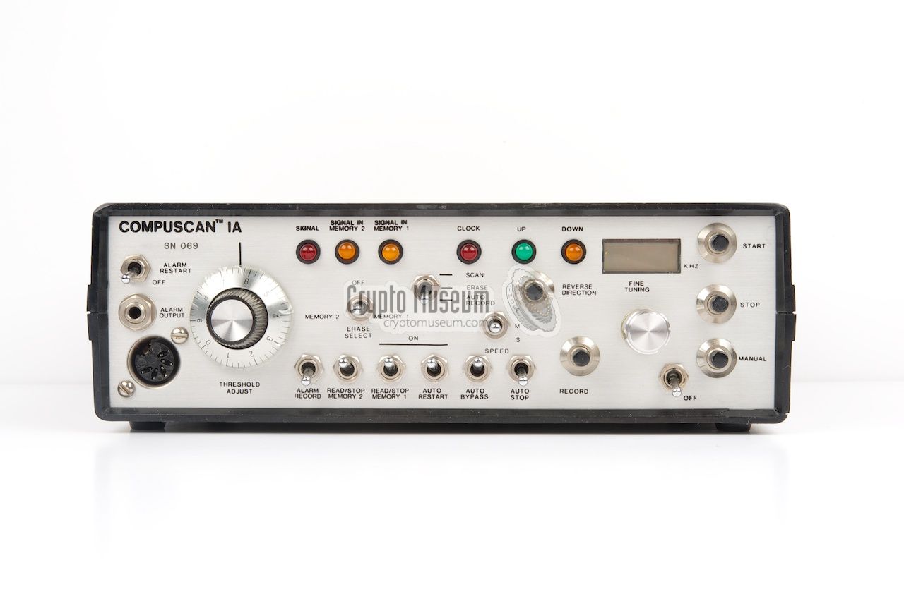
The Compuscan was designed to carry out most of the functions of the
human operator automatically. It was a computer-controlled device
that allowed the signals in a room to be compared with a previously
recorded 'safe area' that was stored in the Compuscan's memory.
The image on the right shows a COMPUSCAN 1A unit that belongs to
a collector in the US.
It was used in tandem with a Scanlock Mark VB and
is connected with it through the DIN socket at the bottom left
of the front panel. A similar socket is available on the front
panel of the Scanlock.
|
|
|
Please note that the Compuscan can only be used in combination
with a Scanlock that has been modified for it. It can be recognised
by the DIN socket marked COMPUSCAN at the front panel, to the right
of the 2MHz IF output. There is also an extra ON/OFF switch to
enable/disable the Compuscan.
It is possible that in the early days, Scanlock
units were modified for this in the US by
TSA, but a later variant
was manufactured in the UK with this connector already present.
The idea behind the Compuscan was developed by
Glenn Whidden at
TSA,
a former technical expert of the
CIA.
It would later evolve
into a series of products known as Glenn's Eagle.
Glenn Whidden is also featured in the Channel 4 documentary
The Walls Have Ears
that is available through the YouTube link below [3].
When the Scanlock Mark 5B
was succeeded in 1984 by the Scanlock 2000,
the old Scanlock Mark 5B
was kept in production especially for the US market,
as it was the only model that was suitable for the COMPUSCAN add-on.
It was sold by TSA.
|
|
|
|
|
|
|
All controls, indicators and connections are located on the front
panel of the unit. This allows the COMPUSCAN to be stored and used
whilst inside the side pocket of the Scanlock Mark 5B's carrying
case. It is connected to the Scanlock via a special cable that runs
from the 5-pin DIN socket at the bottom left, to a similar socket
on the control panel of the Scanlock Mark 5B.
All indicators are nicely arranged at the top of the front panel.
There are 6 LEDs and a small LCD display. The MODE of operation
is selected by the switches at the center, as is the scanning speed.
The ON/OFF switches at the bottom are used to select various features.
The most frequently used operational controls, such as the start, stop
and recording buttons, and the ability for fine tuning,
are all located at the right,
so that they can be operated with one hand.
|
When performing a thorough bug-sweep, the operator would first take
the Compuscan to a so-called safe zone; an area away from the
target that was known to be free of bugs. Compuscan was then used
to record the activity on all frequencies and store this in its
built-in memory 1.
|
He would than return to the target area and perform a full sweep
automatically using the Compuscan. As the Compuscan had recorded
all activity at the safe area, it knows which stations and
frequencies to ignore. As a result, only new signals
(i.e. the eavesdropping bugs) are found.
In the Channel 4 documentary The Walls Have Ears, Scanlock inventor
Lee Tracey
can be seen using a Scanlock Mark VB
with a COMPUSCAN connected to it [3]. The image on the right
was taken from that program and shows a working Compuscan unit
at the top right.
|
|
|
When scanning the target area, the Compuscan/Scanlock searches the
spectrum in 4096 units with a selectable speed, and autmatically
stops when a signal is detected that is not stored in Memory 1 and
that exceeds the current treshold as set with the large knob at the
left. The treshold knob works similarly to a squelch control.
If the operator is away from the unit, any suspected signal can be stored
automatically in Memory 2, so that they can be examined later.
The scanning speed is selectable in three steps: F (fast), M (medium)
and S (slow). The best results are obtained in Slow mode. In that
case a full scan takes approx. 1 minute and 20 seconds.
As the Compuscan is powered by the Scanlock
via the DIN cable, it reduced the Scanlock's battery life
to approx. one hour (when not powered from the mains).
|
|
|
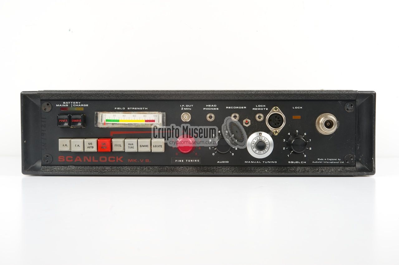
Early model Scanlock Mark VB
Modified for Compuscan
|
 |
|
|
Intially, the COMPUSCAN was connected to a modified - standard -
Scanlock Mark VB.
The modification was probably carried out by
TSA and consisted of the addition of a 5-pin
DIN socket and an ON/OFF switch to the Scanlock's front panel,
and a small PCB that was mounted inside.
The image above shows an Scanlock Mark VB Issue 2 that has been
modified for use with the COMPUSCAN. On this version, the built-in
telescopic antenna has been replaced by an N-type socket.
Furthermore, the red knob that was originally used for manual
subcarrier adjustment, is now used for FINE TUNING and the lettering
has been change accordingly. The odometer-style tuning knob of the original
Scanlock Mark VB
is replaced by a more common multi-turn knob.
|
|
|
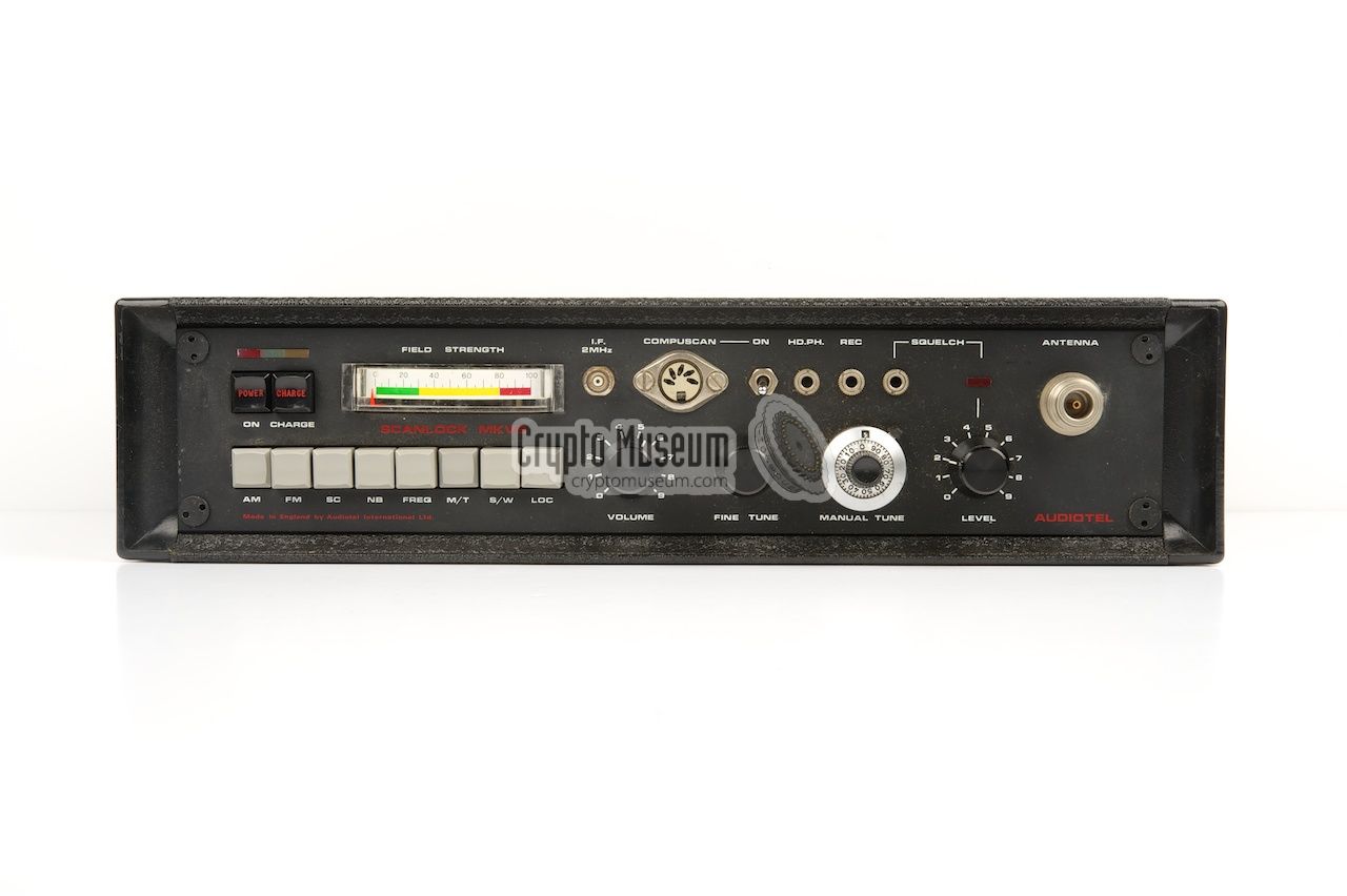
Later model Scanlock Mark VB
Compuscan-ready
|
|
|
|
When the COMPUSCAN became successful, also in the UK, Audiotel decided
to change the design of the Scanlock Mark VB slightly, so that it became
COMPUSCAN-ready. The layout of the front panel was changed, so that the
5-pin DIN socket and the switch fitted in nicely with the rest.
Furthermore, the red knob was replaced by a black one, as it was no longer
used for subcarrier adjustment, and was swapped with the VOLUME adjustment.
It makes more sense as the FINE TUNING is now aside the TUNING control.
The functions of the eight push-buttons at the bottom left are no longer
printed on the knobs but are now screen-printed on the front panel itself.
|
The COMPUSCAN is built inside a standard plastic enclosure that measures
approx. 20.5 x 17 x 6.5 cm. It consists of two identical case shells that
can be separated by removing two long bolts from the bottom of the unit.
After rmoving the upper case shell, the interior becomes visible.
|
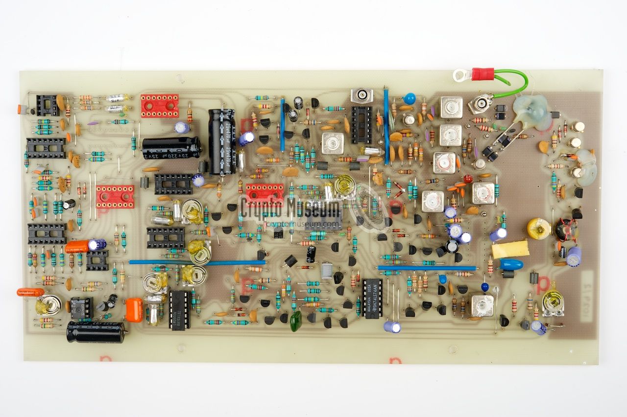
The entire assembly consists of a front panel with all controls, indicators
and the main connector, and three printed circuit boards (PCBs) that are
stacked togetheras a sandwich.
The bottom PCB is mounted to the bottom of the case with
four small screws at the corners. After removing these screws, the entire
assembly can be lifted from the case. The three PCBs are bolted together
with metal mounting posts, and are inter-connected by means of a ribbon
cable at the rear that acts as a backplane.
Several flying wires connect the PCBs to the front panel.
|
|
|
Contrary to what the name 'COMPUSCAN' may suggest, the device does not
contain a computer or a controller of any kind. Instead, it contains
a programmable MC145151 PLL,
manufactured by Motorola [4], and some
computer memory, that is fully controlled by standard CMOS logic ICs.
When disconnected, the memory contents are retained
by a standard 9V battery at the back.
|
The operation of the COMPUSCAN is bst explained by the block diagram
that is presented in US patent 4,368,539, a patent filed on 22 August 1980
by Glenn Whidden in the US. It is the patent on which the Compuscan is based.
Please note that the items in the top left are in fact the Scanlock receiver.
Although it is an external device, it is effectively integrated with the
Scanlock.
|
Updated 26 January 2014
We have received a Scanlock Mark VB issue 3,
which is the COMPUSCAN-ready version, complete with a working
COMPUSCAN unit.
Unfortunately, the Scanlock has been 'demilitarized' by people who
didn't know that this was never a classified item. In the process
of 'demilitarization', most ICs have been removed from their sockets
and all wiring has been cut and removed. Some of the components have simply
been ripped from the PCBs. One IC has been desoldered from the board.
The PSU board is broken into pieces,
probably to get access to the
main board
below it, and even from this board the ICs have been removed.
All wires to and from the front panel controls
have been cut and
removed whenever possible. Luckily, the special
TSA Compuscan modification board
is still present. It is our goal to restore this unit and, if possible,
bring it back to life again.
|
|
|
|
Any links shown in red are currently unavailable.
If you like this website, why not make a donation?
© Copyright 2009-2013, Paul Reuvers & Marc Simons. Last changed: Wednesday, 29 January 2014 - 11:44 CET
|
 |

|
|


![Scanlock Mark VB with a Compuscan on top. Image taken from the Channel Four documentary 'The Walls Have Ears' [3].](img/bbc_cs_large.jpg "Scanlock Mark VB with a Compuscan on top. Image taken from the Channel Four documentary 'The Walls Have Ears' [3].")