|
|
|
|
|

|
Suitcase spy radio set
The Type A Mk.III was a small spy radio set, manufactured
by the Marconi Company in the UK in 1944, close towards the end of WWII.
It was intended for clandestine operations on occupied territory,
by agents, special forces and resistance units.
The transceiver came as a replacement for the rather bulky
Type 3 Mk.II (B2)
and is also known by its SOE-designator Type 21 Mk.III.
|
The Type A Mk.III is in fact a much smaller radio set that could easily
be fitted inside a child's suitcase. It was supplied either in a fiberboard
case, together with a 'spares' box, or in two water-tight containers
(further explained below).
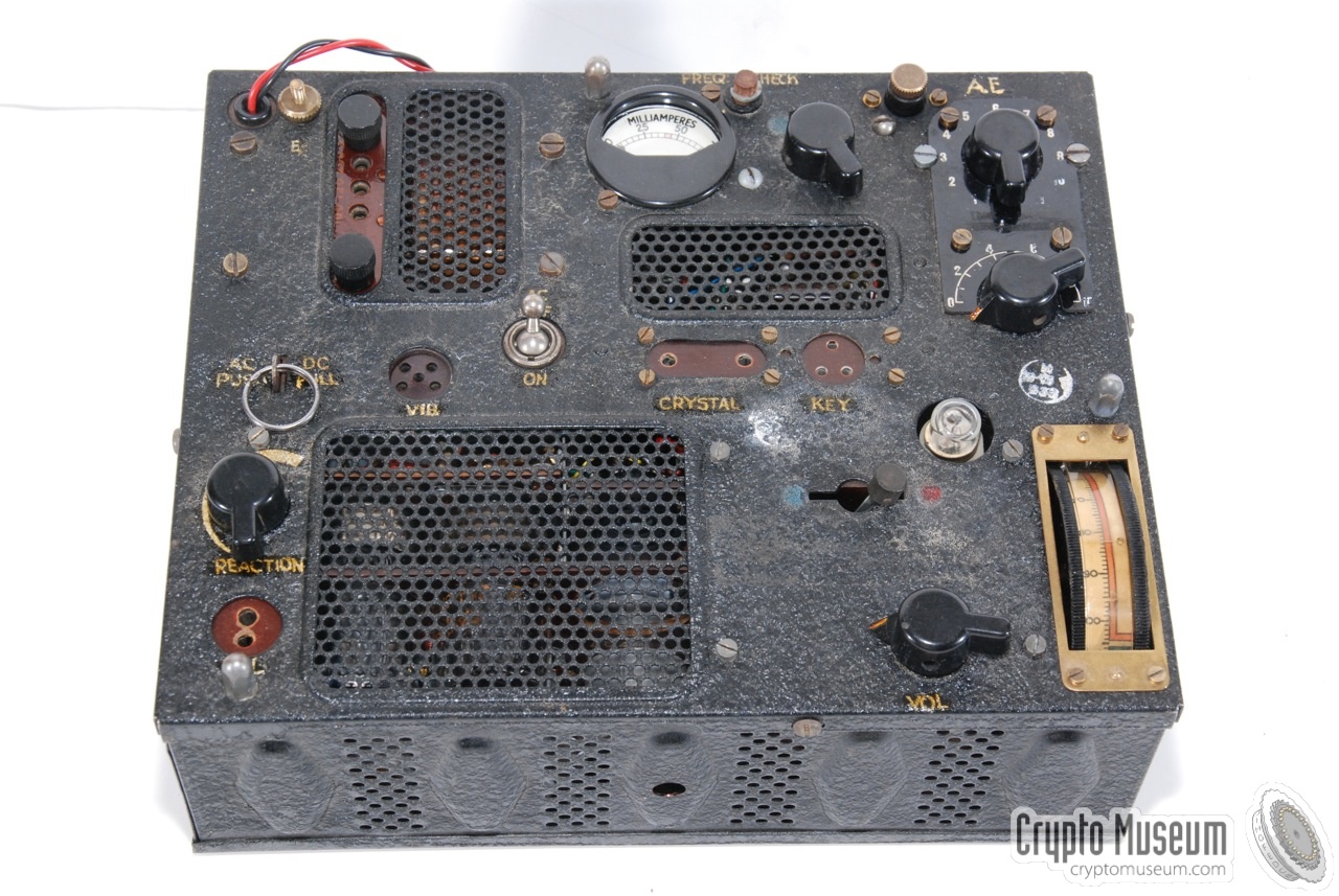
The image on the right shows a bare Type A Mk.III unit.
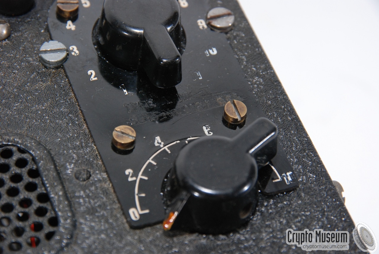
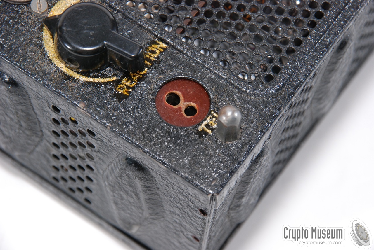
One of its typical design features is the thumb-operated tuning
wheel at the front right.
Although the design of the Type A Mk.III is quite different from its
predecessors, the Type A Mk.II and the Type H15a, it was clearly conceived
by the same design team at the Marconi Co. [1].
|
|
|
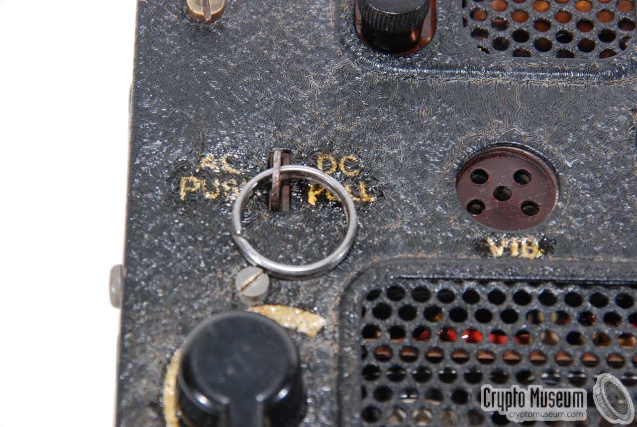
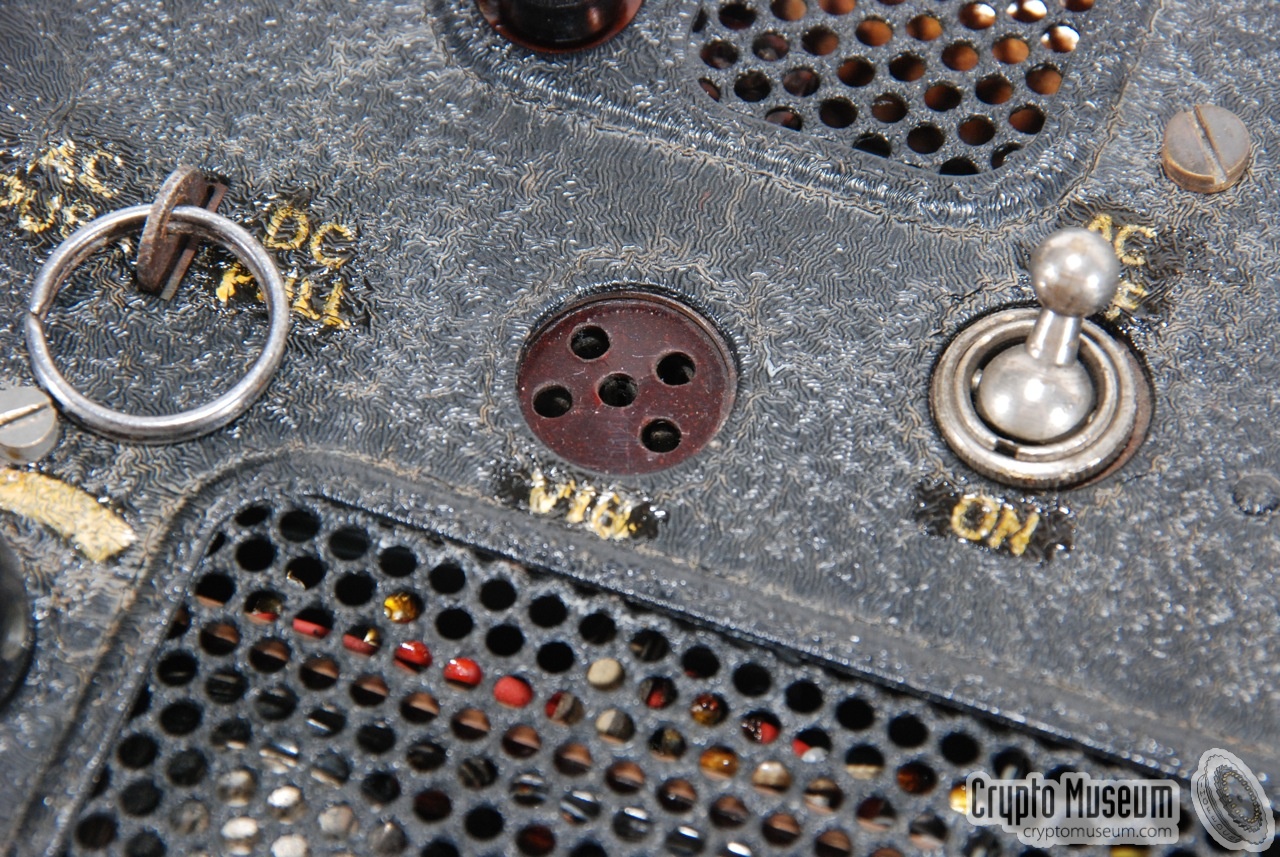
The unit has a built-in transformer, allowing it to be powered directly
from the AC mains (100-130V or 200-250V, 40-60Hz), using the fixed red/black
cable at the top left. At the end of the mains cable
are two banana-type plugs with exchangeable pins, allowing the radio to
be used virtually anywhere in the world.
Alternatively, the radio could be powered by an external 6V DC source
(e.g. a car battery) by using the optional vibrator pack. The vibrator pack
was connected to the 5-pin socket at the front panel
and was usually only supplied with the container version.
The receiver roughly covers all frequencies between 3 and 9 MHz,
divided over two ranges (blue
and red) and has an intermediate frequency (IF) of 1.2 MHz.
The transmitter has a maximum power output of 5W.
The case is perforated at all sides, including the front panel, in order
to provide sufficient cooling when in operation. When building the transceiver
inside a suitcase or a metal container, care has to be taken to maintain
sufficient ventilation.
|
|
|
|
|
|
|
The most common packaging arrangement for the Type A Mk.III was a standard
fibreboard child's suitcase, such as the one shown below. Although the
radio was initially supplied in a slimline red suitcase, this was
often swapped for an alternative one, as it was easily recognised by the enemy.
|
To the left of the transceiver was space for the SPARES-box which was
usually stored on its side. In many cases this SPARES-box was lost
and the accessories, the headphones and the morse key
were simply stored aside the radio.
The lid of the case is padded with felt, with some embossed parts,
so that the transceiver is
well protected during transport.
The image on the right shows an A3 inside an alternative suitcase.
After the war, many A3 radio sets were repacked in such a case,
after the original one had dried-out completely and had
partly desintegrated.
|
|
|
Even during the war, the original case was often replaced for a
less obtrusive one, so that an agent carrying an A3 was not immediately
spotted by the enemy when travelling. In the version shown here, a crystal
is inserted in the crystal socket of the transmitter (center). The
crystal - and any connectors inserted in the sockets -
had to be removed before the case's lid could be closed.
|
The Type A Mk.III was sometimes supplied in two watertight metal containers,
allowing it to be dropped by parachute over occupied territory.
This version was ideal for resistance groups,
as it allowed the transceiver to be stored in moist places for longer period
of times without problems.
|
|
The larger container, marked 'C, held the Type A Mk.III transceiver,
whilst the smaller one, marked 'D', contained the SPARES-box and a
vibrator pack for 6V operation. At this time we don't have a photograph
of this packaging arrangement.
|
|
|
|
- Valves: 7Q7, 2 x 7H7 (receiver) and 7H7, 7C5 (transmitter)
- Frequency range: 3.2-5.25 MHz (blue) and 5.2-9.55 MHz (red)
- Receiver: general coverage
- IF-frequency: 1200 kHz
- AF-output: low impedance headphones
- RX modes: AM R/T and CW
- Transmitter: crystal operated
- TX mode: CW only
- TX Power output: 5W (fundamental frequency) or 3.25W (2nd harmonic)
- Main power: AC 100-130V, 200-250V (40-60Hz)
- Battery power: 6V (4.7A receive, 6.5A transmit)
|
- SPARES-box
- Various crystals
- Spare vibrator
- Spare valves (7Q7, 7H7, 7C5)
- Spare fuses
- Spare neon indicator
- Morse key
- Headphones
- Battery lead
- Bulldog clips
- Mains lamp socket adapter
- Universal plugs for mains lead
- Valve extraction tool
- Various screwdrivers
- Antenna (13m) and ground wire (3m) on Paxolin card
|
- Louis Meulstee, Wireless for the Warrior, volume 4
ISBN 0952063-36-0, September 2004
|
|
|
|
Any links shown in red are currently unavailable.
If you like this website, why not make a donation?
© Copyright 2009-2013, Paul Reuvers & Marc Simons. Last changed: Monday, 31 December 2012 - 10:57 CET
|
 |

|
|