|
|
|
|
|

|
A rare version of Zählwerk Enigma G31
This page is about the Enigma machine with serial number G-111,
a very rare descend of the Zählwerk Enigma family.
At first glance, the machine is very similar to the Enigma G
(Zählwerk Enigma model G31), but features a large socket at it
left side, that has not been seen before.
|
By Paul Reuvers & Marc Simons
In May 2009, the G-111 turned up at aution House Hermann Historica
in Munich (Germany). The machine was offered for sale and would be up for
auction in October 2009.
The machine was in pretty bad condition and on 1 July 2009,
we were given the opportunity
to have a closer look when we visited the auction house.
The results of our investigation are presented on this page and,
in more detail, in a paper that is available for download below.
|
|
|
We should like to thank Frode Weierud in Switzerland for his help in
sorting out the history of the G-111 and the family of machines it belongs
to. His research in the German archives has proven to be invaluable,
and has caused the Enigma history to be rewritten more than once [7].
|
The case of the G-111 is nearly identical to the case of the
standard Enigma G31. The outer dimensions
are 25x27x16.5 cm.
The only difference with the case of a standard Enigma G is the
fact that the lower left side has a hole
to fit the printer connector, as shown in the image above.
|
The table below shows the wiring of the wheels of the G-111,
the entry disc (Eintrittswalze, ETW) and the
reflector (Umkehrwalze, UKW). The Turnover column,
at the right,
shows what letter is visible in the window when the wheel
causes a turnover of the wheel to the left of it.
Please note that these positions are different from the
actual position of the notches on the circumference of the wheel.
Also note that only wheels I, II and V were
present with this machine.
|
|
Wheel
|
ABCDEFGHIJKLMNOPQRSTUVWXYZ
|
Notch
|
Turnover
|
#
|
|
|
|
ETW
|
QWERTZUIOASDFGHJKPYXCVBNML
|
*1
|
|
|
|
I
|
WLRHBQUNDKJCZSEXOTMAGYFPVI
|
ACDEHIJKMNOQSTWXY
|
SUVWZABCEFGIKLOPQ
|
17
|
|
II
|
TFJQAZWMHLCUIXRDYGOEVBNSKP
|
ABDGHIKLNOPSUVY
|
STVYZACDFGHKMNQ
|
15
|
|
III
|
?
|
?
|
?
|
11
|
|
IV
|
?
|
?
|
?
|
?
|
|
V
|
QTPIXWVDFRMUSLJOHCANEZKYBG
|
AEHNPUY
|
SWZFHMQ
|
7
|
|
UKW
|
IMETCGFRAYSQBZXWLHKDVUPOJN
|
*2
|
|
|
|
As we can learn from the above table, the number of notches as well as the
turnover positions of wheels I
and II are identical to those on the same wheels of other Zählwerk machines
(17 and 15 notches respectively).
|
-
This machine contains the standard wiring of the ETW for a commercial machine.
-
The UKW is also wired in the standard fashion for a commercial machine.
|
A very special feature of this particular Zählwerk Enigma, is the
presence of a socket at the left, close to the UKW.
So far, this feature has not been found on any other Zählwerk Enigma before.
The expansion is described in patents DE536556 [4]
and DE595075 [5].
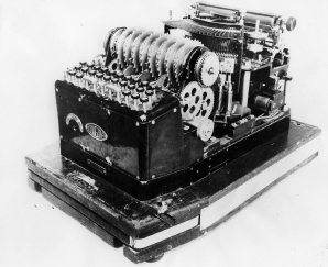
It allows another — much larger — printing Enigma (such as the Enigma H)
to be connected and used as a printing device.
It is believed that the printer connection was an option that was also
available for the Enigma I.
|
When used in this way, the Enigma H (shown in the picture on the right) would
only function as a printing machine; its cipher capabilities were disabled.
Connecting a printer allowed a cipher clerk to decipher any incoming messages
much faster then when reading-off the lamps and writing down the letters.
He could not use the Enigma H
directly, as it wasn't compatible with the
Zählwerk Enigma or the Enigma I.
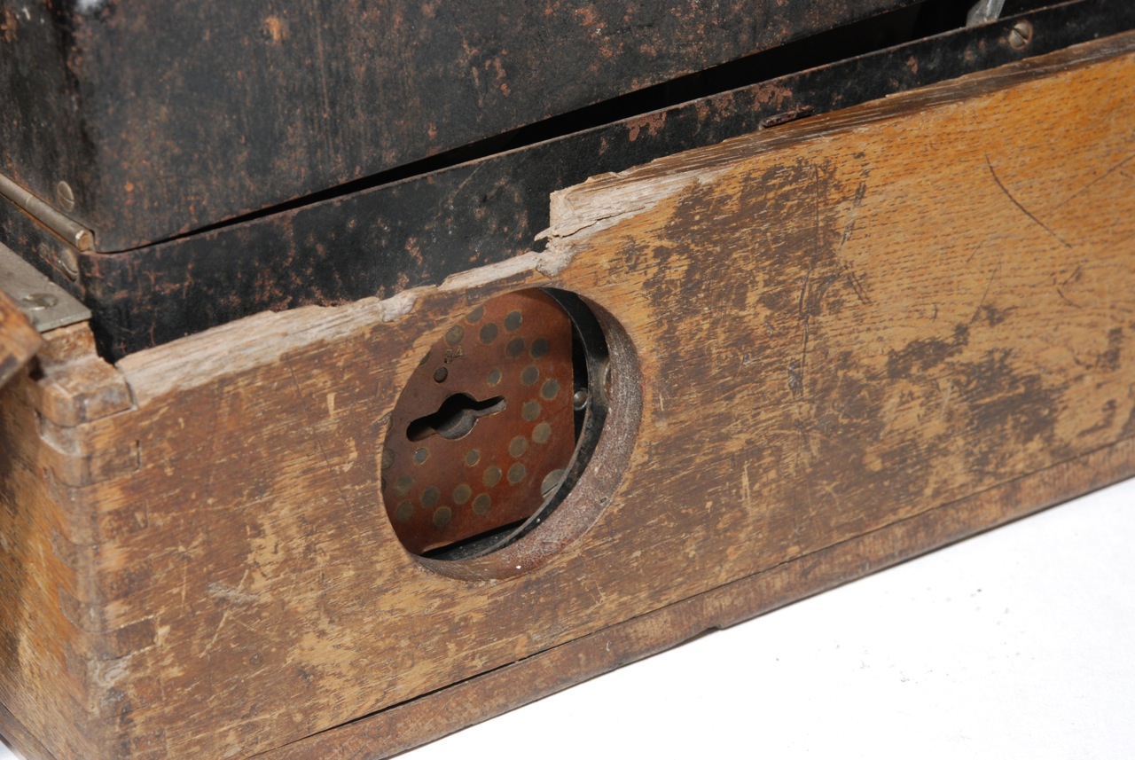
On the G-111, the socket for connection with the Enigma H,
is located at the lower left side of the machine.
A hole of approx. 50 mm is present in the lower part of the metal body.
It gives access to the socket which is mounted behind the hole.
The hole can be closed with a metal cover.
|
|
|
When the machine is mounted inside the protective wooden box,
a circular hole in the side of the box provides access to the socket.
The socket is actually mounted slightly off-centre,
but the hole in the metal body is large enough to accommodate the connector.
|
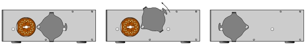
To the right of the socket is an oddly-shaped metal flap that pivots
around an M5 bolt. It can be used to close the socket and protect
its contacts when it is not in use.
The flap has two small folded edges that allow it to be moved with,
say, a finger nail. The upper edge reaches just above the lower part
of the wooden box, so that the flap can be lifted even when the
machine is mounted inside the wooden box.
The illustration above shows how the flap can be moved.
|
The Zählwerk Enigma has 26 lamps on its lamp panel.
These lamps are specified at 3.5 V or lower and are normally powered
by a 4.5V battery. The current trough the lamps is approx. 200 mA.
When the printing device is attached however, the voltages and currents
are much higher, as the machine has to drive the solenoids inside
the Enigma H directly, blowing the lamps as a result.
Removing the lamps was not considered an option, as one had to remove
them each time the printing device was attached
and put them back in again for standard operation.
Therefore a solution was developed which allowed all lamps
to be switched off when the printer connector was placed in
the socket of the machine.
This solution is described in patent DE595075 [5].
|
The patent describes a switch that is operated by the connector itself.
The cable from the printing device has a connector with 28 spring-loaded contacts.
When the connector is inserted into the socket, it must be turned somewhat
in order to lock-in.
When doing so, the contacts of the connector slide into position to make
contact with the circular pads on the socket.
At the same time, another connector — fitted permanently inside the Enigma — is
moved out of position, so that the connection with the lamps is broken.
|
The above drawing shows the rather complex switch that consists of
static and movable parts, both inside and outside the machine.
The connector (not part of the machine) actually behaves as part
of the switch. It has 28 spring-loaded contacts, organized in a zig-zag pattern,
similar to the contact pads on the socket.
At the center is a key that fits the key-hole at the centre of the socket.
|
|
|
The key consists of a rather long cylindrical pin with two 'wings' at the end.
In order to prevent the connector from being inserted the wrong way around,
the wings have different diameters.
The exploded view below should clarify things somewhat.
Please note that during our investigation, we were unable to dismount
the switch assembly and are therefore uncertain about the shape
of the centre part and the cylindrical contacts.
We had to make a few 'educated guesses', based on our knowledge
of the German manufacturing skills.
The same is true for the shape of the connector which we haven't seen yet.
The socket assembly consists of a package of three pieces of pertinax.
The leftmost one is square and is visible from the outside.
The other parts are disc-shaped in order to fit through the
hole in the vertical UKW mounting plate.
The three parts are held together with 4 recessed M3 screws,
fitted from the rear.
The centre part (i.e. the first disc-shaped unit) is smaller
in order to accommodate the wires to the Enigma keyboard.
The switch assembly is inserted into the vertical UKW mounting plate from
the left and is fixed with three recessed M4 screws.
The drawing below shows a cross section of the assembly,
the UKW mounting plate and the rotatable switch.
The spring-loaded contacts of the internal rotatable switch
(to the right of the assembly) are aligned in such a way
that they touch the contact pads of the assembly when
in the default position.
This way, the Enigma lamps are each connected to a switch of the Enigma keyboard.
The spring-loaded contacts of the connector are displaced by approx. 12.8° so that,
when the connector is inserted into the socket,
the spring-loaded contacts do not touch the contact pads of the assembly.
When inserting the connector, the key — that is a permanent part
of the connector — is pushed through the assembly,
into the rotatable switch.
Once the connector is fully pushed in, is is rotated approx.
12.8° clockwise until the internal rotatable switch is locked
in its second position.
A spring-loaded bullet ensures that the switch is kept in place.
The contacts of the connector — that were positioned in between
the contact pads before — are now resting on the contact pads of the socket.
At the same time, the rotatable switch is moved out of position and
its contact are now resting in between the contact pads.
In other words: when the connector is rotated clockwise,
the contacts from the Enigma keyboard to the lamps are broken
and are connected to the external connector instead.
|
The printing connector has 28 contacts, whilst the machine only has 26 letters.
The two remaining contacts were used for the ground line (-)
and the keyboard-release signal.
The drawing below shows a simplified circuit diagram of the
Enigma with the printing switch (A) set to the neutral position.
The standard Enigma power source is connected and the lamps are enabled.
When a key is pressed (W in this case), they current flows in the
usual manner through the drum and a light will be lit (Q in this case).
The red line shows the current.
When a printing device is connected and the switch is enabled (A'),
the Enigma is powered from the alternative source and the
lamps are disabled.
Instead, the output is routed to the printing device.
The drawing below shows how the current flows in that case.
Please note that all parts of the switch move at the same time.
|
Auction house Hermann Historica in Munich (Germany) announced that the
G-111 would be up for sale in the auction of 5 October 2009 at a starting price
of EUR 60,000.
Unfortunately, the machine didn't sell at that auction. This was likely caused
by the current state of the machine, the rather high starting price and the
current economic situation.
Furthermore, this Enigma model is far less common than, say, a war-time service
Enigma, making it less attractive to WWII collectors.
The auction house will review the situation and will probably offer the machine
again in a future auction. Whenever we receive news from them, it will be
announced on this page and in the events
section of this website.
Additional information is available directly from the Hermann Historica website
and it is also possible to order a full-colour catalogue from them.
|
|
|
|
Any links shown in red are currently unavailable.
If you like this website, why not make a donation?
© Copyright 2009-2013, Paul Reuvers & Marc Simons. Last changed: Sunday, 09 February 2014 - 08:39 CET
|
 |

|
|