|
|
|
|
|

|
Online cipher machine
The Telecrypto 53 (TC-53) was an electromechanical wheel-based
cipher machine, developed by
Dr. Edgar Gretener (Gretag)
in Zürich (Switzerland) around 1953.
The machine was initially built for the Swiss Army, but was later also
supplied to other countries, such as Austria. The machine was
based on the earlier TC-35 that was jointly
developed by Edgar Gretener and Boris Hagelin.
|
The rather heavy TC-53 is housed in a large black metal case with a
removable lid at the front and carrying grips at the sides. All controls
and connections are at the front of the machine.
The machine was intended for use with 14-bit teleprinters, such as the
ETK-47,
that were also developed by Gretag. With a special converter unit,
it was also possible to connect the TC-53 to standard
5-bit (baudot)
teleprinter networks.
The TC-53 was an on-line machine that could be used over telephone lines
and via radio links.
The image on the right shows a typical TC-53 that was produced after 1957.
The top section contains the actual cipher wheels that are hidden behind
a hinged panel. The current position of each of the wheels is visible through
12 small windows (4 on the left and 8 on the right). The panel below the
wheels hold the switches that are used to control the stepping of the wheels.
|
|
|
When the machine is not in use, or when it has to be stored or transported,
the front panel can be protected by a removable lid
that also holds the cables, the work light, the
accessories and some spare parts.
At the sides are two handles for carrying the device
(only one is visible above).
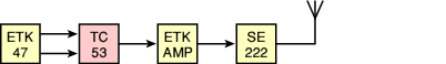
A minimum setup consisted of a TC-53 cipher machine, an ETK-47 teleprinter,
an ETK amplifier, and a standard army field telephone unit.
The TC-53 was connected to the ETK-47 by means of two thick cables, marked
number I and II. Another thick cable connected the TC-53 to the ETK
amplifier, which in turn was connected to the telephone line (via the
field telephone) or a radio set. When operated via radio, it was often
combined with the Zellweger SE222 transceiver.
In 1958, the TC-53 was replaced with the more versatile
TC-58 that could be mounted on top of the
KFF-58 teleprinter.
Like the earlier machines, it used the 14-bit ETK principle,
but offered better sychronisation when used over low quality and noisy
HF radio channels.
As the TC-58 was not compatible with the TC-53, existing TC-53 units remained
in service well into the 1970s.
|
|
|
|
|
|
|
At the top of the front panel is the cipher unit that consists of
twelve cipher wheels. The leftmost four wheels are the actual cipher wheels
(the scramblers), whilst the remaining eight wheels control the stepping
of the cipher unit. The cipherwheels can be accessed through a highed
panel in the top section of the front panel. Stepping is controlled
by the black and red switches.
The lower half of the front panel contains the connections to the
peripheral equipment, such as the ETK teleprinter and the ETK
amplifier. It also has an (optional) connection for an external
14-to-5 bit converter, allowing the TC-53 to be used with standard
5-bit (Baudot) teleprinters.
Two power connections, one for the AC mains and one for a 12V DC
source, are present at the bottom right. When powering from the
AC mains, the voltage selector should match the local mains voltage.
The voltage selector also contains the primary fuse.
A separate 6A secundary fuse is located to the left of the voltage
selector. The main power switch is located above the voltage
selector. The yellow switch is for selecting the mode of operation:
crypto or clear.
|
The following items are stored in the front lid of the machine (dust cover):
|
- ETK connection cable I
- ETK connection cable II
- Main cable
- Work light with flexible arm
- Battery cable (12V DC)
- Lamp puller (rubber sleeve)
- Spare lamps (in metal case at the center)
- Leather carrying straps (optional, not supplied after 1957)
|
The front lid, that is normally used as a dust cover when the machine is
not in use, is also used to store the accessories. Inside the lid are two
compartments. The large compartment at the left has a small (fixed) metal
box at the center, which contains the spare light bulbs, fuses, etc.
Also in the leftmost compartment are the mains power lead and two thick
cables for connecting an ETK teleprinter to the TC-53. The rightmost
compartment is somewhat smaller and is closed with a metal panel that can be
shifted aside. It contains a flexible work light that can be attached to
the right edge of the case of the TC-53 and connects to a socket
at the front panel. It also contains a power cable for connecting
the machine to a 12V DC source, such as a car battery.
|
A complete TC-35 station consists of:
|
- TC-53 cipher machine
- SPG key production unit (optionally built inside the TC-53)
- ETK-47 teleprinter machine
- ETK amplifier
- Army field telephone
|
|
|
Key production unit (SPG)
|
 |
|
|
When using the TC-53, the operator had to set the machine to the daily
key (Grundstellung) plus an additional randomly picked message key. Due to the
way in which the brain works however, such keys are hardly ever random.
For this reason, Gretag developed the SPG, a small key generator
that could be mounted at the center of the front panel of the TC-53.
It was secret and was only supplied to the Swiss Army.
 More information More information
|
|
|
|
The TC-53 was generally used in combination with a Gretag ETK-47
teleprinter that also featured Gretag's unique 14-bit data protocol.
The ETK-47 was a very small telex machine that was connected to the
TC-53 by means of two thick cables, marked I and III.
Althoug it is possible to use the TC-53 with just the ETK-47, it was
often used in combination with the ETK amplifier.
More information
|
|
|
|
When using the TC-53 over a land line, the ETK amplifier had to
be connected to the telephone line, either via a dedicated line interface
unit, or via a standard Swiss Army Field Telephone such as the one shown in the
image on the right.
The field phone shown here was issued to the Swiss Army in 1947 and
was used well into the 1960s. It can be connected to any 2-wire telephone
line and connected to the amplifier of the ETK by means of a short cable with
a 6mm jack at either end. At the front right is the crank of the inductor.
|
|
|
|
The interior of the TC-53 can be reached by loosening 6 large bolts,
marked with a red ring, at the edges of the front panel of the device.
After placing the machine on its back, the interior can be lifted out
by using the two grips at the top and the bottom of the front panel.
When doing so, be careful not to damage any components, such as the red
selenium rectifier at the corner.
|
The image on the right shows the interior of the TC-53 as seen from the
rear right. All components are mounted onto two separate frames that are
held together by the front panel. The upper frame coontains the cipher
wheels and the solenoids for the stepping mechanim. The bright red
component at the top right is a small selenium rectifier used by the stepper.
The lower frame (i.e. the lower half of the machine) contains the power supply
(PSU), the main DC rectifier, several banks of relais, and most of the wiring
to the connectors at the front.
Two relay banks can be swung out towards the rear, as shown in the image on the
right. It allows easy access to the relay banks when repairing a machine,
and also gives access to the large (bright red) selenium rectifier at the center.
Selenium rectifiers replaced valve-based ones in the early 1950s,
but were generally much larger and had a relatively high voltage-drop (1V). [4]
|
|
|
In the early 1960s, they were largely replaced by silicon rectifiers.
Silicon rectifiers are much smaller, less fragile and have a lower
voltage-drop than selenium. As selenium rectifiers are no longer in
production, defective ones can safely be replaced by silicon variants,
but care has to be taken with respect to the DC voltage inside the
machine, which will be higher than before.
|
|
|
|
|
|
|
The TC-53 is a very complex device, mechanically as well as electrically.
The machine can roughly be divided in three parts as shown in the
simplified block diagram below. The blue part at the bottom is the actual
mixer. It performs a modulo-2 operation (XOR) on the input signal (e.g.
from the keyboard) by mixing it with the pseudo-random data stream
generated by the scrambler [5].
The pseudo-random data stream is generated by a bit-pattern generator (yellow)
and a scrambler (red). The rightmost eight wheels are at the heart of a very
complex bit pattern generator. Each wheel has a notched disc at either side
(i.e. 16 discs in total). These discs control 16 switches in the so-called
inversion chain, where a pattern of 32 ones and 32 zeros is generated
(see below).
Of the 32 bits generated by the Inversion Chain, 26 are led to the leftmost
permutation wheel. The remaining 6 bits are dropped. After passing through
all four permutation wheels, the 26 bits are stored in a relay memory.
Four of these bits are used to control the stepping of the permutation wheels
before the next character, whilst 8 bits are used for the Stepping Control
Unit of the bit-pattern generator. The remaining 14 bits are used as the
pseudo-random stream.
|
The stepping control unit is a rather complex circuit that takes 8 bits
from the (14-bit) memory, the settings of the 8 red switches at the front panel,
and the signals from the Z-notches of the 8 wheels, and uses them to control
the stepping of the 8 wheels of the bit-pattern generator.
The Z-notches indicate the position of the letter 'Z' on each of the wheels.
The Stepping Control Unit is constructed in such a way that a minimum length
cipher period is guaranteed. Full details about the exact way in which
the signals are combined, can be found in the circuit diagram [2].
|
Another complex part of the bit-pattern generator is the Inversion Chain
at the top right. It consists of 16 switches that are actuated by the 16
notches discs (one at either side of the 8 stepping wheels). Each switch
generates a logic '1' and a '0' and passes its signals to the next one.
As a result, each switch can invert the output of all switches to its right.
Like this:
The above drawing shows how it works. Each notched disc controls a
so-called cross-switch. The incoming logic '1' and '0' lines, can either
go straight through or be swapped. The output of each switch is used as
the input of the next switch, and so on. Both outputs of each switch
are used to create a bit pattern of 32 bits in total. 26 of these bits
are used as input to the scrambler.
|
Each of the 8 wheels of the bit-pattern generator has two notched discs;
one at either side of the wheel. The wheels were manufactured with all notches
present, so that the customer could configure them at will. By breaking away
several of the notches, a (secret) pattern of notches and gaps is created.
For a detailed description of the notched wheels and the rest of the
pseudo random stream generator, please refer to Walter Schmid's excellent
description of the nearly identical TC-58 cryptogram generator [5].
His book also describes the TC-53 in more detail.
|
Bringing a device like the TC-53 back to life can be really difficult,
especially if the machine has not been used for, say, 10 years.
In our case, the machine exhibited several issues that had to be fixed before
it could be put back to use again.
After slowly raising the mains voltage using a VARIAC, we noticed that
at approx. 60V AC, the transformer started to make a buzzing sound.
This indicated either a broken mains transformer, or a short circuit
immediately behind the transformer. As it turned out, the transformer was
still in one piece, but the Selenium Rectifier (the red
square at the center of the machine) was causing the problem and had to be
replaced.
|
As the existing rectifier is a typical bright red 'landmark' inside
the TC-53, we decided to leave the original one in place and mount a
modern Silicon variant somewhere else. The problem was that the machine
is already tightly packed with components, leaving hardly any space
for this.
After a long search, we found a potential mounting spot not too far
from the original one, reachable from the rear through the upper relay
door of the bottom part. The new square 10A rectifier is
mounted to the bottom
of the upper part and the existing leads are soldered to it.
|
|
|
Next are the electrolytic capacitors. After all these years they likely
to have lost nearly all of their capacity. There are four of these mounted
to the side of the main transformer and can be recognised by their bright
green colour. It would be possible to empty them an put a modern variant
inside. Such modern variants are generally much smaller and have a larger
capacity.
|
When testing the unit, a blow and some smoke indicated that something
was wrong. As it turned out the
mains capacitor had died. This capacitor
is mounted behind the front panel, to the left of the mains socket.
It is a bit difficult to reach, but it should be possible to replace it.
The image on the right shows the old (broken) capacitor and the modern
one that was used to replace it. The white capacitor was packed inside
a shrink sleeve,
in order to hide the fact that it is new.
At the left is the metal bracket that is used to mount the capacitor
to the front panel rear.
|
|
|
At the rear of the TC-53 is a bank of 14 relais (one for each bit of
the 14-element code), each of which has two Selenium diodes, a big
one and a small one. Like the Selenium Rectifier above, such diodes
can be broken after this long time, but it is less likely as the
currents are lower.
If they are broken however, it should
be possible to open them, remove the Selenium discs, and replace them
by a modern diode. The diodes can be recognised by their typical
red and blue end caps. In our case, one of these
diodes had come apart.
As a temporary fix, the diode is now closed with a
short piece of string, as you can see
in the images below.
|
|
|
|
Any links shown in red are currently unavailable.
If you like this website, why not make a donation?
© Copyright 2009-2013, Paul Reuvers & Marc Simons. Last changed: Saturday, 08 March 2014 - 09:26 CET
|
 |

|
|


. Click for more information.")

")


 one")


