|
|
|
|
|

|
Tactical speech security terminal
Spendex-10 was the first wide-band
voice encryption unit developed and built in the early
1970s by Philips Usfa in Eindhoven (Netherlands)
for the Dutch Army.
It uses Delta Modulation (DM)
in combination with a single-bit self-synchronizing Cipher Feedback (CFB)
stream cipher, known as an autoclave,
and was designed to be used in combination with the
Philips RT-3600 radio.
|
In 1960, Philips Usfa started with a range of experiments with voice cryptography for the Dutch Army, under the name Spendex-10.
The design was changed several times,
until a fully operational unit was ready in the early 1970s.
The problems that were demonstrated by the first prototypes were
subsequently solved in the final version: UA-8301/01 in 1973 [2].
The image on the right shows the final version of the Spendex-10.
It is housed in a ruggedized green metal case, similar to that of the
RT-3600 radio used by the Dutch
Army at the time.
|
|
|
All controls are at the front.
The cryptographic key is set by a series of
lever-operated coding switches,
hidden behind a rugged metal door.
As only an officer was allowed to change the daily key,
the door could be locked with a physical key.
Also at the front are the audio-in and audio-out connectors.
All other connectors are at the rear.
Although the Spendex-10 worked as expected and speech intelligibillity was
excellent, the Army did not accept the fact that the addition of speech
cryptography reduced the operational range of the radio by approx. 15%.
The RT-3600 radio was specified for a 15 km range. In practice however,
the unit would easily cover a distance of 20 km. With the addition of the
Spendex-10, the range was reduced to approx. 17 km, which the Army did not
find acceptable.
Development of the Spendex-10 was financed by the Dutch Department of
Defense (DoD), but only a small quantity of them was ever built.
The unit was never taken into full production as the Army did not
give any further orders.
In 1976, the project ended. The units that had been delivered to the
Army would nevertheless be used for several years on
special occasions.
|
|
|
|
|
|
|
Spendex-10 contains a very powerful cryptographic unit,
based on a stream cipher [9].
Data is modified in a non-linear cyclic manner.
The way the data is modified is determined by the daily key. Once the
receiver-clock is synchronized with the transmitter, incoming data is
decrypted immediately whithout the need for further synchronization or framing
(Late Entry Sync).
|
The classification of the Spendex-10 itself was no higher than restricted.
The speech security was determinded exclusively by the key settings,
entered by means of 20 lever-operated coding switches, with 8 positions
each. This produces a total of 820 (1018 or
260) possible
key-settings.
The 20 coding switches are hidden behind an
enforced door at the front.
As the key would only be changed by an authorized officer,
the door can be locked (see the images below).
The appropriate key settings would normally be distributed within the
organisation on paper.
|
|
|
In the first design of the Spendex-10,
ordinary thumbwheel coding switches
were used for setting the key. In the final version however, these were replaced
by the lever-operated coding switches that are clearly visible in the image
above. The advantage of lever-operated switches is that, in case of emergency
or compromise, they can easily be reset to zero in a single action.
For correct operation, the coding switches of all Spendex-10 units in a
(radio) network, must be in the same position. In other words: they have to
use the same key-settings. Operating the device was extremely simple.
Being a simplex device, it would normally be in receive mode.
When switched on, any transmission in progress would immediately be decrypted
(late entry sync), provided that the correct key was used.
Pressing the Push-To-Talk switch (PTT) on the handset, starts an encoded
transmission.
Synchronization, key starting and operation are entirely automatic and
instantaneous. A receiving Spendex-10 automatically differentiates between
crypto speech, crypto data and clear speech [4].
With 260 possible key-settings (60-bit),
it provided extremely good security for its time.
|
|
|
|
|
|
|
Although Spendex-10 was never built in large quantities, the units that
were delivered to the Dutch Army were used on a number of special
occasions. One example of its use is during a train hostage crises
in The Netherlands in the mid-1970s by South Moluccan terrorists.
As the terrorits were expected to use a radio-scanner, Spendex-10
was used as a counter measure.
Another - still unconfirmed - use of the Spendex-10 was during the
movement of nuclear warheads in The Netherlands and Germany in the
1970s and 1980s. Any additional information about these or other
incidents where Spendex-10 was used, are most welcome.
|
Although Spendex-10 can be used with any suitable radio set, it was
designed to be used in combination with the ruggedized
RT-3600 radio,
which was developed in the early 1970s by Philips Telecommunications
Industry (PTI) in Hilversum (Netherlands).
It is one of the best and robust analog military radio sets ever designed and
many of them are still in use today.
|
A typical RT-3600 set consists of the RT-3600 radio itself, plus
one or more additional units and/or accessories. It is often used
with the IC-6320 intercom unit, the AF-3620 speaker unit
and a variety of junction boxes.
The image on the right shows the Spendex-10 mounted on top of the
IC-3620 intercom unit. The RT-3600 radio itself is at the bottom.
The Spendex is connected to the handset-connector of the radio by
means of the 5-pin cable at the right.
The handset itself is
connected directly to the Spendex-10
(to the left of the door).
|
|
|
In the configuration shown here, the Spendex-10 gets its power
from the IC-3620 intercom by means of a
bridge-connector
at the rear, just like the radio.
The IC-3620 is usually powered by a 24V source, such as the
battery of a military vehicle, connected to
the front right of the unit.
|
Spendex-10, or any other voice crypto device for that matter,
requires more bandwidth than just analog speech. Because of all the filtering,
both in the transmitter and in the receiver, the required bandwidth is normally
not available.
That is why the mode-selector of the RT-3600 has an extra setting
marked 'X'. Setting the knob (108) to the rightmost position
bypasses all LF filters and opens the squelch. After that, noise suppression
is taken over by the Spendex-10. Any handsets connected to the
intercom need to be disconnected or silenced in this mode [12].
|
|
|
For more information about the RT-3600 radio station, please refer to
our special pages
about this 'workhorse' of the 70s, 80s and 90s.
In the early 2000s, a large batch of RT-3600 radios was given to the
new Police Force in Afganistan. The radios are also popular with radio
hams.
|
|
|
|
|
|
|
The Spendex-10 is a fully autonomous unit, which is inserted in the audio
lines of both transmitter and receiver. In the description below, it is assumed
that the Spendex-10 is used in combination with
a Philips RT-3600 military radio,
but it can, of course, also be applied to any other transceiver, provided that
the signal levels match.
Delta Modulator
As only digital signals can be enciphered with any level of security,
the analog speech must be digitized first. This can be done with various
techniques, such as Vocoders (e.g. Formant, LPC-10, etc.), Pulse Code
Modulation (PCM) or Delta Modulation (DM) [10]. Choosing the right method is
always a trade-off between cost, size, speech quality and reliability in the
field.

| |
|
Sampling by means of Delta Modulation
|
As Delta Modulation was a Philips specialty at the time, it is used in the Spendex-10. The incoming audio signal (2)
is sampled at approx. 10,000 times per second (1).
Each sample (3) produces a value of
either a '1' or '0' (4).
A value of '1' indicates that the amplitude of the sample is higher than
the previous one.
A value of '0' indicates a relative decrease in amplitude.
The bit rate is equal to the sampling rate and can be set to any value between
7,000 and 30,000 bits per second, by swapping a crystal. In the Spendex-10 it is set to 9,600 bits per second.
Delta Modulation (DM) requires no synchronization bits at all and is far less
sensitive to errors in the transmission path. Error rates of up to 5% still
produce a reasonable level of intelligibility, whilst a 1% error rate is
already enough to put PCM out of business.
Improved versions of DM, such as CVSD and ΔΣ-Modulation
are still widely used today, e.g. in Bluetooth headsets.
CVSD was also used in the later Spendex-50 crypto phone.
Transmitter
Analog clear speech, e.g. from a handset, is filtered first, so that only
signals between 300 and 3400 Hz are left. It is then amplified to the desired
level and fed into the Delta Modulator, where the analog clear speech is
translated into a digital bitstream of 9600 bits per second.
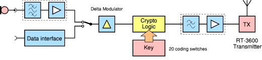
| |
|
Spendex-10 Transmitter Block Diagram
|
The output of the Delta Modulator is then fed into the Crypto Logic, where
it is modified (see below).
The operation of the crypto logic is determined exclusively by
the 20 coding switches.
The digital bit-stream at the output of the crypto logic
is then passed through a low-pass filter
and amplified to the desired level for the transmitter.
Spendex-10 is equipped with a special data interface through which digital
information can be transmitted at speeds up to 600 baud. Incoming data is
detected by the Spendex automatically, and will override any voice mode.
Receiver
The received signal is first filtered, amplified and shaped.
A regenerator is used to eliminate the effect of disturbances
and supplies a clean signal to the crypto logic. If the key-settings of the
receiver are identical to those of the transmitter, the crypto logic
produces the original raw bit stream from the transmitter's Delta Modulator.
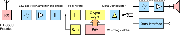
| |
|
Spendex-10 Receiver Block Diagram
|
Feeding the output of the crypto logic into a Delta Demodulator,
produces an approximation of the original voice.
After filtering and amplification, the signal is sent to the speaker.
At the right is also the data interface. The Spendex-10 will automatically
recognize data from speech by detecting specific characteristics
in the data stream.
Crypto Logic
The actual Crypto Logic shown in the block diagrams above, consists of three
functional parts that are further explained below.
The first functional part is a Randomizer (RND).
It uses a Linear Feedback Shift Register (LFSR) to
modify the bit-stream from the Delta Modulator
in such a way that repeated patterns of alternating 0s and 1s
at the input of the crypto-units are avoided.
Additional logic is used to make the behaviour of the RND non-linear.
If the operation of the RND could be kept secret, it would produce
a powerful encryption on its own. At present, there are no known cryptanalytical
attacs against it, other than exhaustive search [9].
For military use this is insufficient
however, as it would be security by obscurity.
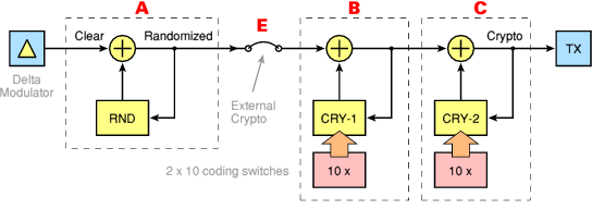
| |
|
Spendex-10 Crypto Logic Block Diagram
|
The modified stream from the RND (A) is fed into the
encryption unit which consists of two identical cascaded cryptographic
units (B)
and (C).
Each bit from the scrambled bit-stream is modified twice (XOR)
depending on the state of the previous crypto-bit.
Each crypto-unit performs a series of complex non-linear feedback shift
operations, the variables of which are determined by the settings of
the coding switches. The algorithm used for this is still classified.
The above diagram shows the operation of the Crypto Logic in transmitting
mode. The bitstream from the Delta Modulator is processed in the order
ABC.
When receiving, order of the blocks is reversed to CBA.
The raw bitstream is first decrypted by the two crypto units and then
de-randomized by the RND, before it is fed to the delta (de)modulator.
In order to add an extra layer of security, it was possible to insert an
extra (external) encryption unit between the RND and the crypto
units (E). Such an external cryptographic unit could be connected
to socket 10 at the rear.
In transmitting mode, the order would then be AEBC.
|
Like most other military equipment, the Spendex-10 is completely modular.
The case is nearly identical to that of the RT-3600 radio and can be opened
both from the front and the rear, by loosening 2 sets of 4 hex-bolts.
The interior consists of two parts that can be extracted easily.
They are connected together by means of a male/female 25-way sub-D connector
(DB25).
|
The Rear Unit is extracted from the rear and contains the power supply unit
(PSU) and the connectors to the outside world (expansion). The Main Unit
is extracted from the front and contains all functional units and controls.
The image on the right shows the complete interior with the Main Unit and
the Rear Unit connected together. All the electronics are hidden inside a
series of cassettes (modules or units) that are plugged-in to the bottom PCB.
Each cassette contains two separate PCBs and it held in place by a bolt at
the bottom.
|
|
|
In the image above, each module is given a number by means of a label on top
of the cassette. The numbers are highlighted here in red.
The modules have the following functions:
|
- Output amplifier and filter, Input circuit
- Time base, Regenerator, Squelch combiner
- TX/RX control, Randomizer, External Crypto
- Crypto units 1 and 2
- Delta Modulator, Mic amplifier, Phone amplifier, Data interface
- Power Supply Unit (PSU)
|
After loosening the locking bolt at the bottom,
a module can easily
be removed by lifting its two handles.
A metal stub at the bottom
prevents the module from being inserted the wrong way around.
The PCBs are removed from the silver-plated case, by removing the
two bolts at the top.
|
Although the two PCBs inside each cassette are
'sandwiched',
they are completely independant and have no connection
between them. Each PCB has its own connection
to the bottom plane.
The image on the right shows a close-up of the Delta Modulator PCB.
It demonstrates the high level of engineering at
Philips Usfa in those days (1973). The PCB contains
first-class components from a variety of manufacturers.
It also contains
µA709 operational amplifiers and a collection of TTL ICs.
Such components became available to the general public much later.
|
|
|
The images below show more details about the sandwich construction
of the PCBs inside each cassette. The cassette is 'guided' by
two metal pins on the bottom PCB. A locking bolt at the bottom
prevents the cassette from 'vibrating' out of its slot.
The construction is similar to that of the RT-3600 radio.
The rightmost image shows the PSU module extracted from the Rear Unit.
|
A number of connections is available at the rear of the Spendex-10.
Below each connection is a number in the die-cast aluminium body.
At the far left is the fuse (7). Immediately to the right of that is
the power connector (8). Although this is a rather complex connector,
only two lines are used (+) and (-).
The reason for using this connector is to allow the Spendex-10 to take
its power directly from the IC-3620 intercom with a short cable,
just like the RT-3600 radio.
|
At the center are two identical connectors. The leftmost one (9) is for
connection to a modem, in order to connect directly to a line-of-sight
radio link, like the FM-200 transceiver.
The connector to the right of it (10) can be used to insert an extra
encryption device between the randomizer and the two crypto units.
This allowed an (optional) extra layer of security that could be added
at a later date if necessary. Crypto and clear data is normally not
available at this connector. By applying a voltage to a specific pin,
external crypto can be inserted.
|
|
|
The rightmost connector (11) is the data connector. The socket is of
the same type as the other two (9 and 10), but only 3 pins are used:
data-in, data-out and GND. This connector allowed digital data to
be sent encrypted via the Spendex-10 at speeds up to 600 baud.
|
The key-setting switches at the front of the Spendex-10 can be protected
against accidental or unauthorized changes, by locking the metal door.
Depending on the level at which the Spendex-10 was used, setting the
daily key might have been a task exclusively for the crypto-officer.
|
However, if the crypto-officer got lost at the battle field,
the radio operator would be unable to change the setting of the
cryptographic key the next day. To overcome the problem of
the lost key, a spare key was hidden inside a sealed compartment
inside the Spendex-10.
The compartment was accessed by removing the Rear Unit from
the case. Looking into the case from the rear reveals a sealed
circular object to the right of the DB25 connector.
The key is held in place by silicone foam.
After breaking the seal, the operator could remove the key.
|
|
|
The image above shows the spare key being removed from the secret
compartment. Once the key was removed, the operation would re-assemble
the Spendex-10 and open the door to the key-setting switches, in order
to change the daily key. The rightmost image below, shows the key
storage compartment seen from the inside of the Spendex-10.
|
Development of the Spendex-10 started as early as 1960 with a range of
voice encryption experiments. Several solutions and methods were tried
and the design was changed frequently. This eventually led to the
final version in the the early 1970s, the UA-8301/01 shown above.
|
Before the UA-8301/01 however,
the prototype UA-8301/00 was used to test the usability of the set.
Although the prototype was electrically more or less identical, there were
a number of physical differences, such as the type of thumbwheels,
the PSU, the connections at the rear
and some physical aspects of the case and the interior.
In July 2012, an original prototype of the UA-8301/00 turned up completely
unexpected. It is shown in the image on the right, complete with a suitable
power supply unit mounted below it. It has serial number 002 and was
built in 1969.
|
|
|
After evaluating the UA-8301/00 prototypes, a number of design changes
were carried out. The connections at the rear were changed in such a way
that they matched with the
RT-3600 radio set that was developed
simultaneously at Philips Telecommunications in Hilversum (Netherlands).
The standard thumbwheels were replaced by lever-operated types in order to
allow easy zeroizing, and the physical design of the locked door in front
of the thumbwheels was replaced by a more practical design. The door was given a better lock and a spare key was to be hidden inside the rear compartment of the unit. It could be used in case of an emergency (see above).
|
The most important changes however, were made in the interior of the Spendex 10.
In the prototype the autoclave (crypto logic) was built around a series
of early ICs (e.g. the FCH132) that required
negative voltages, whereas the final version contained standard TTL logic ICs.
Similar changes were made to the other plug-in units.
The new crypto logic would no longer integrated with
the thumbwheels but became separate plug-in units.
All electronics, except for the power supply, were moved from the
rear compartment
to the front compartment.
|
|
|
As a result, the front compartment became larger and the 'wall' between
the front and rear section had to be moved. In the final design, the rear
compartment would only contain the power supply (voeding) and the connections
to the RT-3600 radio set and the matching intercom.
In October 1972, the revised UA8301/01 design was ready, but the user
manual [4] had already been finalized. As a result, the manual still
contained a large number of photographs of the UA8301/00 prototype version
and only a few that were taken from the new design.
|
|
|
|
|
|
|
- Interview with a former Philips employee
Eindhoven, July 2011.
- Philips Usfa, Internal Memo L/5636/AvdP/JG
23 August 1982, page 5.
- Philips Usfa, Spendex 10 leaflet
Document number 13806/E, January 1973.
- Philips Usfa, Spendex 10, Tactical Speech Security Terminal
Spendex 10 user manual / short description.
13916/E. December 1972.
- Philips Usfa, Spendex 10 Technical Description (2)
UA-8301/00. 13902/N. December 1969. 3/5-TH11-.../2.
- Philips Usfa, Spendex 10 Technical Description (3)
UA-8301/00. 13902/N. December 1969. 3/5-TH11-.../3.
- Philips Usfa, Spendex 10 Technical Description (Draft)
UA-8301/01. 21 November 1972.
- Wikipedia, Linear Feedback Shift Register
- Wikipedia, Stream cipher
Retrieved December 2011.
- Wikipedia, Delta modulation (DM)
Retrieved December 2011.
- Stukken betreffende het project Spendex 10. 1974-1976 (Dutch)
Nationaal Archief, Den Haag, Ministerie van Defensie: Generale Staf;
Staf van de bevelhebber der landstrijdkrachten (Landmachtstaf),
(1969) 1973-1979 (1980),
nummer toegang 2.13.110, inventarisnummer 1632.
NL-HaNA, Generale Staf, 2.13.110, inv. nr. 1632.
- Konklijke Landmacht, Technische Handleiding, RT-3600 (Dutch)
Bediening en 1e echelons onderhoud. 28 October 1974.
|
|
|
|
Any links shown in red are currently unavailable.
If you like this website, why not make a donation?
© Copyright 2009-2013, Paul Reuvers & Marc Simons. Last changed: Sunday, 03 March 2013 - 16:59 CET
|
 |

|
|


")


 mounted on top of an RT-3600 radio set.")

 mounted on top of an RT-3600 radio set.")


")


")
")
")
 with PSU (bottom)")
")
")
")
")


")


")
