|
|
|
|
|

|
Recorder Detector
The TRD-800 was a small body worn recorder and bug detector developed and
built by Research Electronics Inc. (REI)
in Cookeville (Tennissee, USA) in 1989. It can be worn inconspicuously
and allow RF devices, such as bugs and surveillance radios, and body worn
recorders to be detected, giving the operator a covert (vibrator) warning.
|
In the 1970s and 80s, tape recorders (and sometimes even wire recorders)
were a common means for covertly recording conversations, for example
during infiltrations, for espionage and in diplomatic traffic (e.g.
embassy meetings).
Whilst recording a conversation, the recorder usually erases a previous
recording by using a so-called erase head; an electromagnetic device that
scrambles the particles on the magnetic tape. This is usually done by applying
a high-frequency AC signal to the erase head. The TRD-800 was able to detect
these frequencies.
|
|
|
For this to work, the TRD-800 had to be very close to the recording
device. In fact it had to be within the electro-magnetic field of
the erase head. As the size of this field is usually no more than 10 to
20 cm, the antenna of the TRD-800 had to be moved over the body of the subject.
In order to do this covertly, the operator would place the
antenna on his wrist, held in place with an elastic wrist band,
with the cable running through his sleeve to the detector that was hidden,
say, in his pocket. Whilst greeting the person, he could inconspicuously
move his hand around the person under test. If a reording device was detected,
the TRD-800 provided a feedback signal to the operator through the LEDs
at the front panel or through the built-in vibrator.
As the TRD-800 also contains a built-in RF detector, it is capable of
detecting radio transmitters (bugs) too.
During the cold war, tape recorders were a popular means for covertly
recording a conversation, using miniature tape recorders such as
the Protona Minifon, the Nagra SN or even small pocket memo recorders.
Since the introduction of digital recorders (often integrated in mobile
phones), tape recorders have been gradually phased out. As a result,
the TRD-800 is no longer available from the manufacturer and the RF
detection feature is covered by other TSCM products.
|
|
|
|
|
|
|
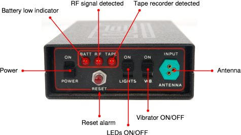
All controls of the TRD-800 are at the front panel as shown below.
The unit is turned ON/OFF with the slide switch at the left, whilst
the dual mode antenna is connected to the green 3-pin socket at the right.
The two switches at the right are used to control the LEDs and the vibrator.
The red LED indicators are at the front panel. The leftmost one will light
up when the battery voltage is getting too low and the battery needs to be
charged. The middle LED lights up when a strong RF signal is picked up,
for example from a radio bug. In areas with strong local radio stations,
it might be necessary to press the RESET button after turning the unit on.
The rightmost LED will light up when a tape recorder is detected. At the
same time the vibrator gives a signal.
|
Considering the era in which the TRD-800 was developed,
is extremely well built. The unit is housed in a fully metal enclosure
that consist of two half case shells, held together by 8 small (hex) bolts.
The detector is powered by a built-in 7.2V rechargeable NiCd battery pack.
|
Inside the case is a small L-shaped double-side PCB with all components
neatly mounted at the top side. At the bottom of the unit is the 7.2V
NiCd battery pack that can be charged with the supplied mains adapter.
The cut-out space in the PCB is used by a cubical vibrator, visible in
the image on the right at the top centre.
The LEDs and the switches
are all mounted onto a vertical sub-PCB that
is soldered onto the main board. The 3-pin antenna socket is wired
directly to the main PCB. This is done to avoid broken tracks from
frequent plug movements.
|
|
|
In order to protect the design of the TRD-800, the text has been
removed from all of the ICs.
Although the unit shown here is over 20 years old by now, it is still
in excellent condition. Surprisingly, we were able to recharge the
battery again after all these years, and use the TRD-800 for several
hours. The battery is charged by connecting the supplied adapter
at the rear.
|
- Research Electronics Inc., Unit Operating Instructions, Model TRD-800
Original User Guide. Date unknown, but probably 1989.
|
|
|
|
Any links shown in red are currently unavailable.
If you like this website, why not make a donation?
® Copyright 2009-2013, Paul Reuvers & Marc Simons. Last changed: Tuesday, 21 May 2013 - 11:29 CET
|
 |

|
|


 battery pack.")


