|
|
|
|
|

|
Stasi Intercept Receiver
- under construction
The 2170 was a communications receiver
developed by Institute für Nachrichtentechnik Berlin
(Institute for Communications Technology) and built by
VEB RFT Funkwerk K÷penick,
both in Berlin (Germany) in the early 1980s.
The 2170 is a rather large highly modular receiver that came
with a number of plug-in units.
It was ideally suited for intercept tasks and was easy to operate.
|
The 2170 was the successor to the 2070 series and had the advantage
that it could be remotely controlled.
As the 2170 was heavily used by the Stasi for intercept
of domestic and foreign radio signals, it is also known as the
Stasi Receiver.
The 2170 consists of three main building blocks: a receiver unit (EE),
a control unit (BE) and a power supply unit (SE).
It covers all frequencies in the VHF and UHF band
from 25 MHz up to 1 GHz in CW (A1), AM (A3) and (F3).
The 3 building blocks are each housed in their own 19" rack,
and are mounted together in a single case.
|
|
|
The image above shows a typical 2170 receiver that was found in
the main Stasi operations center in Berlin-Lichtenberg,
just after the fall of the Berlin Wall in 1989.
The upper part contains the power supply unit (PSU). It consists
of several modules each of which is responsible for a specific voltage.
The mains power switch is at the top right.
The section in the middle is the actual receiver. It consists of
three modules (the RF section, the IF section and the demodulator)
that can be swapped in order to support different
frequency ranges and bandwidths.
The lower part is the control unit where all controls and read-outs
are nicely arranged. It is constructed in such a way that the entire
2170 unit can be placed on a table in front of the operator.
The frequency can be adjusted at the bottom left of the control unit.
Depending on the model, a jog dial or a toggle lever is used.
In practice, most operators preferred the toggle lever.
It allows the frequency band to be search with a speed proportional
to the position of the lever.
At the center of the control unit is the
digital frequency readout. At the right is the AF amplifier with a
small speaker at the front. A DIN socket at the front allows a
pair of headphones to be used instead of the built-in speaker.
Due to the modular construction, it was possible to adapt the
2170 for a variety of applications, frequency ranges, bandwidths,
modulation arts, etc.
|
|
|
|
|
|
|
- SE - Stromversorgungseinheid (Power Supply Unit, PSU)
- EE - Empfangeinheit (Receiver Unit, RX)
- BE - Bedienungseinheit (Control Unit, CU)
|
The following RF plug-in units are available:
- 2170 HF
- 25 - 36.5 MHz
- 36.5 - 53 MHz
- 53 - 67 MHz
- 67 - 87 MHz
- 2170 HG
- 87 - 108 MHz
- 108 - 144 MHz
- 144 - 174 MHz
- 174 - 240 MHz
- 2170 HC
- 340 - 320 MHz
- 320 - 400 MHz
- 400 - 480 MHz
- 2170 HD
- 480 - 680 MHz
- 2170 HE
- 680 - 820 MHz
- 620 - 1000 MHz
|
The following bandwidths can be selected on the IF unit:
|
- 3.2 kHz
- 7.5 kHz
- 12 kHz
- 30 kHz
- 300 kHz
|
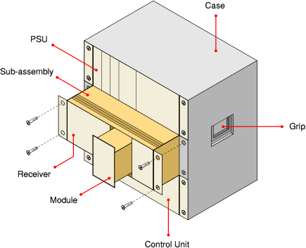
The 2170 is housed in a rather heavy metal case with all controls
at the front and all connections at the rear. At each side is a
grip, allowing the case to be lifted by two persons.
The case consists of three sub-assemblies: the PSU, the actual
receiver (RX) and the control unit (CU). Each sub-assembly is housed
in its own rack that can be extracted by removing the 4 bolts at
the edges (2 at either side). The sub-assembly can than be pulled
from the main case.
Each sub-assembly consists of a number of (removable) modules.
Each module has a wide DIN connector at the rear that connects it
to a socket in the sub-assembly frame. The sub-assembly itself
is slotted into the main case and is connected to the other
sub-assemblies via a set of connectors at the rear and permanent
wiring inside the case.
|
The receiver consists of three modules: the RF stage, the
IF stage and the demodulator. The AF stage is part of the control unit.
These three modules can be swapped easily by pulling them out
of the sub-assembly frame from the front.
The receiver covers all frequencies between 25 MHz and 1 GHz,
divided over 14 ranges that are spread over 5 different plug-in
units (modules).
|
Please note that this page is currently under construction
and that new information will be added as and when it becomes
available. In due course we hope to be able to publish the
full circuit diagram of the 2170 receiver. Due to the bad
quality of the photo copies, the circuit diagram has to be
restored first. If you have any additional information about
this receiver or its use, please contact us.
|
|
MfS
|
|
Ministerium für Staatssicherheit
Ministery for State Security of the former DDR (East Germany);
one of most effective and repressive intelligence and secret police
agencies in the world.
The agency is commonly known as Stasi, which is the abbreviation of
Staats-Sicherheit, and had its headquarters in East-Berlin.
The Stasi had strong ties with the Russian intelligence service
KGB.
(Wikipedia)
(Wikipedia Germany)
|
|
Stasi
|
|
 Ministerium f³r Staatssicherheit
|
|
|
|
Any links shown in red are currently unavailable.
If you like this website, why not make a donation?
® Copyright 2009-2013, Paul Reuvers & Marc Simons. Last changed: Tuesday, 08 April 2014 - 09:25 CET
|
 |

|
|