|
|
|
|
|

|
Automatic bug finder
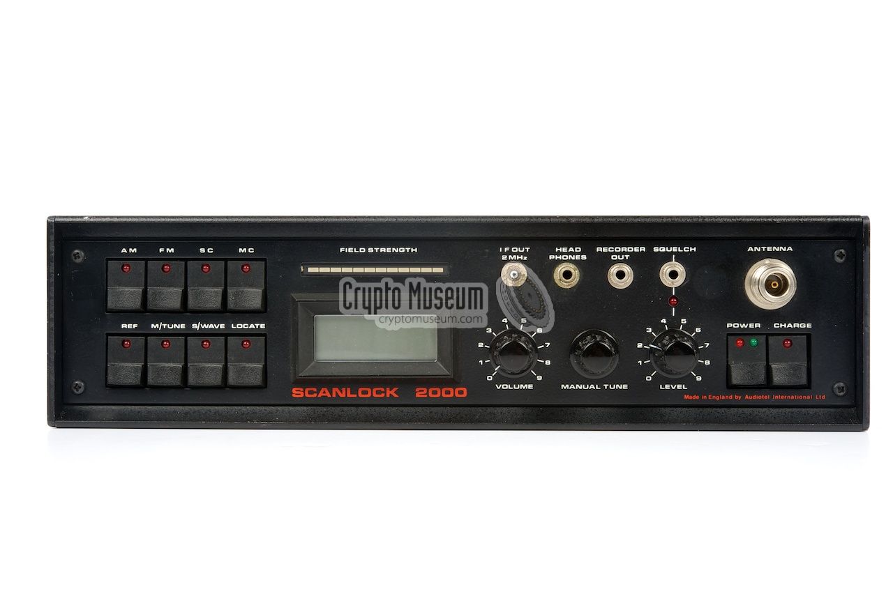
Scanlock 2000 was a TSCM receiver (bug finder),
developed and built by Audiotel Ltd. in Corby (UK)
in 1984 as the successor to the highly acclaimed
Scanlock Mark VB. It is based on the same
design but features a wider frequency range and simplified controls.
Furthermore it had a digital readout and a LED-based field strength meter.
The design was based on the original Scanlock,
invented by Lee Tracey in the early 1960s.
It was succeeded in 1990 by the Scanlock ECM.
|
The unit is housed in a metal case and
measures 33.5 x 22 x 8 cm, the same as its predecessor.
It looks like an ordinary portable transistor radio and was usually
delivered in a leather carrying bag with a spare battery
in a compartment at the bottom. It could also be used outside
the case on the shoulder, as it has its own carrying strap.
All controls and connections are located at the front panel, except
for the mains power socket that is located at the right side.
The unit can be powered from the mains or by the built in 16.8V
NiCd battery that is charged from the mains.
|
|
|
Compared to its predecessor, the Scanlock Mark VB,
it had a better build quality with double-sided PCBs, a fully metal case
(the Mark VB had plastic side panels), a simplified control panel,
a wider frequency range (up to 4 GHz) and the ability to find power
line bugs (mains carrier). The built-in telescopic antenna has been
replaced by a N-type socket, which has helped expanding the frequency
range. Apart from these differences the main principle has been
left unchanged.
The Scanlock 2000 can scan the entire frequency range between 10 MHz
and 4 GHz in just a few seconds and will automatically lock onto
the strongest signal. When a bug is turned on, the Scanlock will
lock virtually instantly if the bug is within its range.
In areas with strong broadcast transmitters
it might be necessary to move around the room in order to find bugs
that appear to be weaker than the broadcast station(s).
In addition it is possible to tune the Scanlock manually,
using the 10-turn frequency adjustment on the control panel,
and the LCD as an indicator.
Strangely, the Scanlock 2000 is lacking a connector for the
COMPUSCAN, something that was present
on later versions of the Scanlock Mark VB.
For that reason, the Scanlock Mark VB was kept
in production for the US market for several more years, whilst
the Scanlock 2000 was the mainstream product on the European market.
It was replaced in 1990 by the Scanlock ECM.
|
|
|
|
|
|
|
All controls of the Scanlock 2000 are at the front panel (or the top
panel when it is used in the upright position). At the left are eight
Digitast push-buttons that are used to select the current mode
of operation and the type of modulation. Each MODE-switch has its own red LED.
To the right of these buttons is a field strength meter consisting
of green, yellow and red LEDs, and a digital tuning indicator. Note that
this display doesn not shows the current frequency (as it wouldn't
make sense anyway), but rather a number
that is related to the internal tuning voltage.
The right half of the control panel contains the connections and the
manual adjustments. At the top right is the N-socket for connection of
a telescopic antenna, or an external antenna connected via a coax cable.
The switches at the bottom right are for power and charging.
|
The Scanlock ECM can be used in a variety of modes and with
various types of modulation,
depending on the type of bug, the method of searching
and the time available to do the sweep. The following modes are available:
|
- Automatic mode
In this mode, the Scanlock searches fully automatically for bugs in the
room and locks itself onto the strongest signal that it finds, with a lock
sensitivity of 1mV up to 2 GHz and a somewhat reduced sensitivity between
2 and 4 GHz. In earas with strong broadcast transmitters, it may be necessary
to move the receiver around the room whilst searching.
- Manual mode
When searching for bugs with an extremely low RF output signal, or in areas
with strong broadcasting stations or other sources of interference, it might be
useful to conduct a manual search. In manual mode, the Scanlock has a typical
sensitivity of -70 dBm up to 2 GHz. In this mode, the frequency can be adjusted
by turning the multi-turn knob
(with the built-in counter).
Furthermore the meter can be used as a frequency indicator.
- Soundwave mode
In this mode, the Scanlock emits a continuous (audible) tone, that changes
to an intermittent tone when the receiver detects itself (i.e. if it
is heared through the bug).
This mode should be used as a last resort, as it is likely to alert the
eavesdropping party of the fact that a bug-sweep is taking place.
- Locate mode
When the LOCATE button is depressed, the Scanlock provides an audible
tone with a pitch that is proportional to the strength of the acquired
signal. Starting off with a low frequency ticking sound, the pitch gets
higher when approaching the bug. In this mode, the use of a pair of
headphones is advised, as otherwise the eavesdropping party might become
aware of the fact that a bug-sweep is taking place.
- Power line mode
When pressing the MC button, the Scanlock 2000 is capable of detecting
power line bugs (mains carrier bugs). For this it is necessary that
the Scanlock 2000 is powered by the mains that is checked, as it uses
its own power connection as 'antenna'.
If there are any power line intercoms or PLC modems in the building,
you will probably hear them immediately.
In this mode, the rest of
the Scanlock receiver is unused and the field strength meter will be off.
Note that an MC check has to be carried out on all wall sockets, as
some of them may be powered from a different phase.
|
The Scanlock 2000 is suitable for reception of the following types
of modulation:
|
- AM
This is for bugs that use Amplitude Modulation (AM).
Not many bugs are of this type. It is generally used with low-frequency
transmitters (below 80 MHz).
- FM
This is for the most common type of bugs that use
Frequency Modulation (FM). These bugs generally operate at frequencies
from 80 MHz onwards. Most of the cheaper commercial and homemade bugs
are of this type.
- Subcarrier (SC)
With some of the more sophisticated bugs, the audio is modulated onto
a non-audible subcarrier. As a result, the bug appears to be sending a
silent carrier, whereas in fact it carries all of the sound it picks up
in a room. In this mode, the Scanlock will adjust itself automatically
to the required subcarrier frequency.
- Mains Carrier (MC)
This setting checks the incoming mains power supply for so-called
power line bugs. In this mode the entire receiver is bypassed and
the field strength meter is not used either.
|
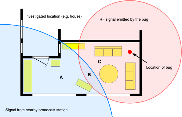
Operation of the Scanlock 2000 is remarkably simple. All you need to do
when first scanning a room for potential bugs (sweeping) is to turn on the
receiver and select FM to search for the most common type of FM radio bugs.
The Scanlock will now automatically lock onto the strongest signal in its
vicinity, as illustrated below:
With the receiver in location A, the Scanlock will probably lock immediately
onto a strong broadcast station that is nearby. Such broadcast stations are
generally much stronger than a potential bug in the room. When the Scanlock
is moved around the room however, it will continue to scan and lock onto
the strongest signal. When the receiver is in location B it will
intermittently switch between the broadcast station and the bug, but when
it is moved closer to the bug (C) the RF signal from the bug will be
stronger than the broadcast station and the bug will be heard.
|
|
|
Searching for power line bugs
|
 |
|
|
The Scanlock 2000 can also be used for finding power line bugs.
Such bugs use the mains power line as their transmission medium
and generally operate between 25 kHz and 260 kHz. Especially for these
type of bugs, Scanlock 2000 has a built-in Mains Carrier (MC) demodulator.
For this to work, the Scanlock 2000 has be powered from the mains,
rather than from the internal batteries.
Searching requires all wall sockets to be checked.
Let us consider the following example:
In this case, a power line bug is mounted inside a wall socket at the
bottom right (A). As this wall socket is connected to the R-phase of
the house's mains network, it can not be detected from the wall socket
at location B, which is connected to the T-phase. Wall socket C however,
will yield a positive detection as it is connected to the same phase
as the bug.
|
The Scanlock 2000 can be powered from two different sources:
directly from the 110 or 220 V AC mains,
using the built-in power supply unit (PSU), or by
the built-in rechargeable 16.8V NiCd battery. At the right side is a socket
that accepts a Euro-style mains cable,
plus a fuse holder.
|
The battery is 22 x 44 x 293 mm and consists of 14 NiCd cells of 1.2V each,
delivering a total of 16.8V and 1.2 Ah. They should be charged for 14 hours
with 120 mA. When fully charged, the battery allows 5 to 6 hours of
uninterrupted use.
The battery compartment is located below the mains socket, at the bottom
of the receiver. It is accessible through a
flap in the leather carrying case.
After removing the panel
of the battery compartment, the battery can be removed.
A spare battery
can be stored in a compartment at the
bottom of the leather carrying case.
|
|
|
Powering the surviving Scanlock 2000 receivers from their
internal batteries
today, will not be easy. Most of these old NiCd cells will be
worn out by now
or will have started leaking,
and it will be difficult (if not impossible) to
find suitable replacements. Nevertheless it should be possible to construct
a (mechanical) equivalent from modern NiMH or Li-ION cells in a plastic holder.
|
The Scanlock 2000 was usually supplied with a number of accessories,
such as a leather carrying case, a spare battery, a pair of headphones,
an external telescopic antenna and a so-called 'Magic Wand'.
In addition, some third party accessories could be used as well.
Some examples:
|
In order to visualize a small section of the frequency spectrum,
it was possible to connect an external Panoramic Display or
Spectrum Monitor to the scanlock, via the 2MHz IF socket at the
front panel. It makes it possible to find small low power bugs
operating at a frequency very close to a strong broadcast station.
A suitable Spectrum Monitor (SM-1 and later the SM-2) was developed
by Glenn Whidden of TSA.
 More information More information
|
|
|
|
The Scanlock 2000 has an internal speaker through which the audio
from the intercepted bug can be heared. As this might alert a potential
eavesdropping party, it might be better to use a properly isolated pair
of headphones, or a small pair of earphones, such as the ones shown here.
The headphones can be connected to the 3.5 mm (mono) jack socket on the
control panel.
|
|
|
|
Although the Scanlock was commonly used with the built-in telescopic
antenna, it was also possible to use an external device, such as
the so-called 'Magic Wand'. This was a smaller antenna that could be
used to search locally, for example by moving around the room.
As the original Magic Wand is missing from our Scanlock, an alternative
one is shown in the image on the right. It was taken from a
CPM-700 bug finder.
|
|
|
|
For training purposes, Audiotel created the simple MCX Power Line Bug,
that is shown in the image on the right. It consists of a small PCB that
is powered from the mains. A sensitive microphone picks any sound,
and the modulator injects the signal back onto the mains.
More information
|
|
|
|
The Scanlock 2000 is largely based on the design of the
Scanlock Mark VB. Despite the digitast buttons
and the digital readout on the control panel, the Scanlock 2000 is a
fully analog device. In order to understand its operation, we need
to consider the block diagram below:
There is no preselection other than a filter that allows only frequencies
above 10 MHz to pass by. The 10 MHz output of the first local oscillator
is fed to a so-called comb generator. This is effectively a non-linear
junction (i.e. a diode) that causes harmonics of the fundamental frequency
to be generated. It produces signals at 10 MHz, 20 MHz, 30 MHz,
40 MHz, etc.
The output of the comb generator is then mixed directly with the antenna
signal, resulting in many frequency segments of 10 MHz each, being superimposed
on top of each other. The problem of sweeping the entire spectrum between
10 MHz and 4 GHz has now been reduced to sweeping just a single small segement
of 10 MHz, by sweeping all superimposed segments simultaneously.
By using a sweeping oscillator in the 2nd IF stage, the resulting 10 MHz
segments can be swept in less than a second. The receiver locks onto the
strongest signal found.
At the output of the 2nd IF stage, a 2 MHz signal is available for further
processing. It is fed to the three demodulators (AM, FM and SC), and is
also available on a connector at the front of the receiver, to allow the
connection of a panoramic display, such as the
SM-2 Spectrum Monitor.
In Sound Wave mode (S/W), the speaker produces a continuous 1800 Hz
tone. The output of all demodulators (AM, FM, SC and MC) is checked
for this tone by applying it to a sharp 1800 Hz filter. When this
particular frequency is detected, the tone is changed into an
intermitted one.
Compared to the earlier Scanlock Mark VB,
has an additional detector for finding mains carrier bugs (MC).
Such bugs generally use an LF signal (e.g. 120 kHz) to carry the audio
signal over a pair of mains wires. The MC decoder is connected directly
to the mains. This method has its drawbacks as it only checks the
Live and Neutral wires of the mains and not the Earth.
Furthermore it can not be used to check other types of cables, such as
telephone lines. These problems were overcome in the later
Scanlock ECM, which had a separate receiver
for frequencies below 10 MHz and used an external LF interface for the
3-wire mains and other types of cables.
|
The interior of the Scanlock 2000 can be accessed by removing the
top panel that is held in place by four bolts at the top and one
at the right side. The Power Supply Unit (PSU) is mounted on the
inside of the top panel and is wired to the rest of the receiver,
so care has to be taken here.
|
The main board of the Scanlock is mounted at the bottom of the
case. The professionally made double sided PCB has all
components mounted on the top side. It is shown in the image
on the right. The circuit in the upper right corner is the
first mixer that produces the 0-10 MHz signal.
The PSU is on a separate board mounted on the inside of the top panel,
together with the mains transformer and the battery charge circuit.
The front panel consists of two sandwiched PCBs that are connected
to the main board and the PCB by means of three removable (socketed)
flatcables.
|
|
|
Compared to the earlier Scanlock Mark VB,
the construction of the case and the PCBs of the Scanlock 2000 is
much better, although the design of the circuit and its operation
is nearly identical. Furthermore, the text is no longer removed
from the ICs as a copy protection.
|
|
|
|
Any links shown in red are currently unavailable.
If you like this website, why not make a donation?
© Copyright 2009-2013, Paul Reuvers & Marc Simons. Last changed: Saturday, 01 February 2014 - 08:55 CET
|
 |

|
|


")


")
 and LCD")


")


