|
|
|
|
|

|
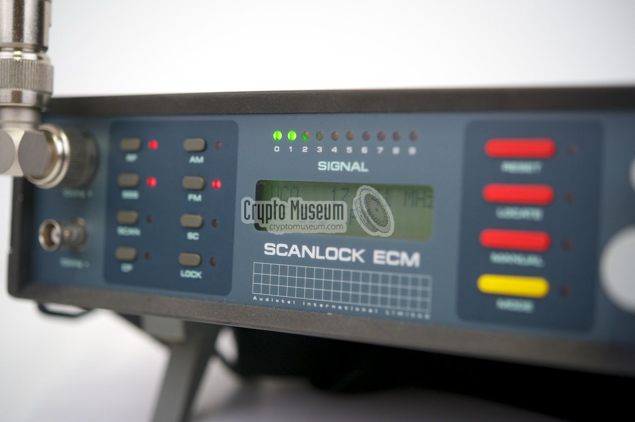
Automatic bug finder
The Scanlock ECM was a Countermeasures Receiver (bugfinder),
developed in 1990 by Audiotel in Corby (UK) as the successor
to the Scanlock 2000. It uses the same novel harmonic
scanning technique as its predecessors,
but also offers a number of new facilities and operational modes.
|
Like earlier Scanlock receivers, the ECM can quickly scan the entire
frequency spectrum between 10 MHz and 4 GHz for radio bugs with
Amplitude Modulation (AM), Frequency Modulation (FM) or Subcarrier
Modulation (SC).
In addition, the Scanlock ECM can detect Mains Carrier (MC) transmitters
(power line bugs) and Current Carrier bugs.
Unlike its predecessors, the ECM can also be used as a full-coverage
radio scanner, with accurate frequency readout.
In addition, an LF mode is present to detect eavesdropping devices
operating below 10 MHz.
|
|
|
The Scanlock ECM contains an harmonic receiver that is nearly identical
to earlier designs in the Scanlock Mark VB
and the Scanlock 2000.
All parts of the Scanlock ECM are under digital control and the
analogue local oscillator has been replaced by a digital PLL, allowing
accurate frequency readout.
Operation of the Scanlock ECM is not straightforward and requires good
reading of the manual and understanding of the operating principle of
the various modes. As an aid to the non-technical user, a number of
built-in presets can be selected from a menu via the LCD display.
The Scanlock ECM superceeded all previous Scanlock models, but does not
have a memory function that allows signals to be compared to those from a
safe zone, like the
Compuscan add-on
for the Scanlock Mark VB did.
Apart from that, the Scanlock ECM was a very versatile and compact
bug tracer that allowed quick location of
radio bugs, mains bugs and other cable bugs.
In 1992, the ECM was followed by the Scanlock ECM Plus
that eventually evolved into the Scanlock Select Plus
in 1996. It introduced signal analysis and comparison to previously stored
scan data, and was the last logical step towards the fully PC-driven
Scanlock M2
in 2000 [2].
|
|
|
|
|
|
|
All controls of the Scanlock ECM are nicely arranged at the front panel
as shown in the diagram below. Nevertheless, operation of the receiver is
not straightforward and requires in-depth knowledge of the principles
behind it, not least because many different devices have been integrated
into one compact portable design. To help the unexperienced user,
a number of preset programs are selectable from a menu (using the yellow
button marked 'MODE').
At the left are two antenna inputs, one for all RF frequencies between
10 MHz and 4 GHz (N-connector) and one for all CF frequencies below
10 MHz (BNC connector). For the RF and CF bands, two independent receivers
are used. To the left of the display are 8 push-buttons that are used
for selecting the type of modulation (AM, FM, SC, CP) and the type of
scanning (SSS, SCAN and LOCK). The receiver can search for the Strongest
Signal (SSS) or scan the entire band slowly (SCAN). LOCK mode is identical
to the Sound/Wave mode (S/W) of earlier
Scanlock receivers.
To the right of the display are buttons for manual frequency control
(MANUAL) and for accessing the menu's (MODE and RESET). The LOCATE
button is used to activate the bug-locating mode, in which the speaker
will produce a Geiger-type ticker that gets faster when you approach the bug.
|
|
|
|
|
|
|
The Scanlock ECM can be used in a variety of modes and with
various types of modulation,
depending on the type of bug, the method of searching
and the time available to do the sweep. The following modes are available:
|
- Strong Signal Search (SSS)
In this mode, the Scanlock ECM searches fully automatically for bugs in the
room and locks itself onto the strongest signal that it finds, with a lock
sensitivity of 1mV up to 4 GHz.
In earas with strong broadcast transmitters, it may be necessary
to move the receiver around the room whilst searching.
- Manual mode (SCAN)
When searching for bugs with an extremely low RF output signal, or in areas
with strong broadcasting stations or other sources of interference, it might be
useful to conduct a manual search. In manual mode, the Scanlock has a typical
sensitivity of -70 dBm up to 2 GHz. In this mode, the frequency can be adjusted
by turning the multi-turn knob
(with the built-in counter).
Furthermore the meter can be used as a frequency indicator.
- Soundwave mode (LOCK)
In this mode, the Scanlock emits a continuous (audible) tone, that changes
to an intermittent tone when the receiver detects itself (i.e. if it
is heared through the bug).
This mode should be used as a last resort, as it is likely to alert the
eavesdropping party of the fact that a bug-sweep is taking place.
- Locate mode (LOCATE)
When the LOCATE button is depressed, the Scanlock provides an audible
tone with a pitch that is proportional to the strength of the acquired
signal. Starting off with a low frequency ticking sound, the pitch gets
higher when approaching the bug. In this mode, the use of a pair of
headphones is advised, as otherwise the eavesdropping party might become
aware of the fact that a bug-sweep is taking place.
- Cable mode (CF)
When pressing the CF button, the Scanlock ECM is capable of detecting
power line bugs (mains carrier bugs, or MC) or bugs that are connected to
other types of cable. For this, the external LF interface is used.
It is suitable for both the mains and for other types of cables, and should
be connected to the lower antenna input (10 MHz -).
If there are any power line intercoms or PLC modems in the building,
you will probably hear them immediately.
Note that an MC check has to be carried out on all wall sockets, as
some of them may be powered from a different phase.
- Telepone line bugs (RF)
Telephone bugs are usually common radio bugs that are connected to the
telephone line. They are commonly powered by the telephone line itself
and are only activated if the line is in use.
A special interface is supplied to allow telephone line bugs to be
effectively detected and traced. The interface is connected in place of
the telephone set.
|
The Scanlock ECM is suitable for reception of the following types
of modulation:
|
- AM
This is for bugs that use Amplitude Modulation (AM).
Not many bugs are of this type. It is generally used with low-frequency
transmitters (below 80 MHz).
- FM
This is for the most common type of bugs that use
Frequency Modulation (FM). These bugs generally operate at frequencies
from 80 MHz onwards. Most of the cheaper commercial and homemade bugs
are of this type.
- Subcarrier (SC)
With some of the more sophisticated bugs, the audio is modulated onto
a non-audible subcarrier. As a result, the bug appears to be sending a
silent carrier, whereas in fact it carries all of the sound it picks up
in a room. In this mode, the Scanlock will adjust itself automatically
to the required subcarrier frequency.
- Cable Frequencies (CF)
This setting allows the mains power network and/or any other cables
and cable networks to be checked for bugs. With transmitters of this type,
such as power line bugs,
the audio is often modulated onto a carrier of 120 kHz or higher.
The Scanlock ECM can detect such carriers and demodulate them automatically.
|
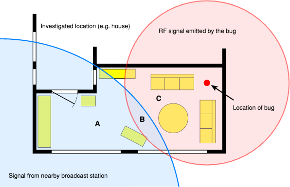
Finding rado bugs with the Scanlock ECM is remarkably simple. All you need to do
when first 'sweeping' a room for potential transmitters, is to select Strong
Signal Search (SSS) and Frequency Modulation (FM) to find the most common type
of bugs. The Scanlock will now automatically lock onto the strongest signal in
its vicinity, as illustrated below:
With the receiver in location A, the Scanlock will probably lock immediately
onto a strong broadcast station that is nearby. Such broadcast stations are
generally much stronger than a potential bug in the room. When the Scanlock
is moved around the room however, it will continue to scan and lock onto
the strongest signal. When the receiver is in location B it will
intermittently switch between the broadcast station and the bug, but when
it is moved closer to the bug (C) the RF signal from the bug will be
stronger than the broadcast station and the bug will be heard.
|
The Scanlock ECM can also be used for finding bugs that use an arbitrary
pair of cables as their transmission medium. A well-known example of such
a 'parasite' is a Power Line Bug, also known as a Mains Carrier Bug.
Other cable pairs however, can also be used for this purpose (see below).
|
Bugs of this type, generally superimpose a modulated carrier
between 25 kHz and 260 kHz onto the cable. As the carrier frequency
is too high for the human ear, they are not noticed.
Especially for these types of transmitters, the Scanlock ECM has
a built-in Cable Frequency (CF) receiver that covers all frequencies
below 10 MHz. It should be used with the supplied LF interface that
is shown in the image on the right. One end of the LF interface is
connected to the 10MHz- input of the Scanlock ECM whilst the other
end is connected to a mains wall socket.
|
|
|
As the mains network generally consists of three wires (Live,
Neutral and Earth) and the bug only needs two wires, a rotary
switch on the LF interface should be used to determine which wire
pair is to be investigated (L-E, L-N or N-E). Note that this feature
is new to the Scanlock ECM.
The earlier Scanlock 2000 only checked for
bugs connected between Live and Neutral. The new method was later
als used in the separate TCM-03 Cable Checker.
Searching for power line bugs requires all wall sockets to be checked.
We will use the following situation as an example:
In this case, a power line bug is mounted inside a wall socket at the
bottom right (A). As this wall socket is connected to the R-phase of
the house's mains network, it can not be detected from the wall socket
at location B, which is connected to the T-phase. Wall socket C however,
will yield a positive detection as it is connected to the same phase
as the bug.
|
Mains power cables are by no means the only threat for carrying
eavesdropping signals. In theory, any pair of cables that is
present in the target room can be used as a possible medium.
Examples of such cable pairs are the speaker cable of the stereo,
intercom cables, alarm cables and the thermometer cable of the
central heating. Cables of this type can also be checked with the
LF interface by connecting a flying lead with two crocodile type
clips to it, as shown in the image on the right. In this case,
the rotary switch should be set to the far right (CABLE).
|
|
|
The crocodile clips are now connected to the wires to
be investigated, but note that the input voltage supplied to
the CABLE socket should not be too high.
The LF interface can only be used for one cable pair, so the
mains plug has to be removed when checking other types of cables.
To ensure this is done, a sliding panel
over the input sockets prevents the use of the
other socket.
|
|
|
Searching for telephone bugs
|
 |
|
|
With the appropriate interface, the Scanlock ECM can also be used
for tracing telephone bugs. As bugs of this type are generally only
activated when the line is active (i.e. the phone is in use),
tracing them requires special tactics. The supplied Scanlock
Telephone Interface is used for this.
|
First, one has to establish whether the bug is inside the telephone set,
or connected to the line. If the Scanlock ECM picks up a bug when the
handset is lifted, a bug has been positively detected.
Next, the telephone set should be replaced by the Scanlock Telephone
Interface shown in the image on the right. It is connected to the telephone
line, the Recorder output of the Scanlock (at the rear) and the RF input
(front).
Picking up the handset can now be simulated by sliding the LINE switch
to the right. This 'claims' the line and should cause the LED to light up.
|
|
|
If at this stage, no radio signal is detected, the bug was probably
placed inside the telephones set. The telephone set should not be
checked for typical phone bugs, such as a
replacement microphone.
If however, the radio signal is still detected when the line is
engaged, we can assume that the bug is connected to the telephone
line. The line should be checked physically.
|
The Scanlock ECM was generally supplied with a number of accessories
and training devices, packed together in a large sturdy flightcase.
From the inventory in our Scanlock ECM kit and the user manual, we
have assembled the following list of items that were available:
|
- Scanlock ECM, main unit
- Flightcase
- User Manual
- Telescopic antenna with N-connector (HF)
- Telescopic antenna with BNC socket (LF)
- Right-angle N-connector
- Various radio bugs (for training)
- Power line bug (for training)
- Telephone interface
- Low Frequency interface
- Remote Alarm
- BNC antenna lead
- Telescopic hand antenna with BNC
- Headphones
- Mains lead
- Shoulder strap
|
The purpose-made flight case is designed
inside such a way that all items are nicely stored in their own
tight-fitting compartments.
The receiver is stored in the large rectangular space at the centre.
Around the receiver are the telephone interface, a power line bug
the LF interface, the external alarm and an (optional) FM/Subcarrier
bug. Additional devices and training bugs can be stored in the
remaining spaces. Cables and headphones are stored beneath the
Scanlock ECM.
|
In order to get acquinted with the Scanlock ECM and with finding
bugs, it is necessary to train regularly with the equipment.
For this purpose, Audiotel
and other manufacturers supplied a range of
training bugs.
Some of these were real bugs that were converted
for training use.
|
For training purposes a small radio bug in a metal enclosure
was often supplied with the Scanlock ECM. Offering two types
of modulation (FM and SC) it can be used as an ordinary FM
radio bug as well as a subcarrier bug.
Please note that the possession and use of this type of bug
might be subject to local laws.
 More information More information
|
|
|
|
For training purposes, Audiotel created the simple MCX Power Line Bug,
that is shown in the image on the right. It consists of a small PCB that
is powered from the mains. A sensitive microphone picks any sound,
and the modulator injects the signal back onto the mains.
More information
|
|
|
|
For traning purposes, a variety of RF bugs were used. Although Audiotel
offered a range of battery powered radio transmitters, some users
preferred the powerful Mactron Mark II shown in the image on the right.
It was crystal based and was powered by a standard 9V battery.
It is shown here with an external plug-in mike.
Please note that the possession and use of this type of bug
might be subject to local laws.
More information
|
|
|
|
Another professional bug that was often used for training purposes,
is the so-caled Phone Mike Bug,
a small RF transmitter that looks exactly like the standard microphone
of an old telephone handset.
It was powered by the telephone itself and was only on the air when
the handset was picked up.
More information
|
|
|
|
The Scanlock ECM is housed in a heavy aluminium case that can be
accessed by removing the top panel (when the receiver is in horizontal
position). The batteries and the speaker are mounted to the inside
of the top panel and are connected to the main unit by means of flying wires.
|
The interior
roughtly consists of three parts: the main board that
contains all analogue and digital components, a Power Supply Unit
(PSU) that is mounted at the right side (when seen from the front)
and the controls board with the LCD display that is mounted behind
the front panel.
The main board
takes up most of the available space inside the receiver.
In consists of a professionally designed double layer PCM with all
first class components mounted on the top surface. The image on the
right shows the harmonic receiver,
located in the rear left corner.
|
|
|
The other parts of the main board contain the separate
CF receiver, for frequencies below 10 MHz,
the audio circuits,
with tone and ticker generators for the LOCK and LOCATE modes,
and the AMD 87C521 microcontroller.
A separate I/O chip is used for driving
the LED bar.
|
|
AM
|
|
Amplitude Modulation
|
|
CF
|
|
Cable Frequency (signals below 10 MHz)
|
|
FM
|
|
Frequency Modulation
|
|
HF
|
|
High frequency (signals above 10 MHz)
|
|
LF
|
|
Low Frequency (signals below 10 MHz)
|
|
MC
|
|
Mains Carrier / Mains Cable
|
|
RF
|
|
Radio Frequency (signals of 10 MHz or higher)
|
|
SC
|
|
Subcarrier modulation
|
|
SSS
|
|
Strong Signal Seeking
|
|
|
|
Any links shown in red are currently unavailable.
If you like this website, why not make a donation?
© Copyright 2009-2013, Paul Reuvers & Marc Simons. Last changed: Saturday, 01 February 2014 - 09:07 CET
|
 |

|
|


")


")


 and HF antenna (right)")


")


